

Commands in normal ARM programming are 32 bit, this means despite being a RISC processor, the ARM has a wide variety of commands and clever functions such as the barrel shifter, and a wide range of addressing modes.
However, there may be times when using 32 bit commands is impractical due to their size, such as when writing embedded firmware and bytes are limited
The Thumb mode was designed for times when 32 bit commands are excessive. In "ARM Thumb" mode all commands compile to 16 bits / two bytes. Although there are more limited commands, overall we will be able to do the same tasks with much less space. Despite using 16 bit command bytes, all the registers are still 32 bits, and all the commands function in 32 bits � it's just the resulting byte code that has haved.
ARM Thumb still has a varied instruction set, however it's much more limited compared to ARM, and in some ways resembles 68000 style code.
Arm Thumb has many limitations, some of the most significant are:
1. The 'Barrel Shifter' is not available as part of the addressing modes, we have dedicated ROR, ASR LSR and LSL commands in Thumb.
2. Auto Increment and Decrement are not possible, except with the LDMIA/STMIA commands. We do now have dedicated PUSH and POP commands to work with the stack.
3. Condition codes are set automatically, we can't use the 'S' suffix to define which commands set flags.
4. Individual commands can not be conditionally, we can only use conditional branches, such as BCC and BEQ to jump over code we don't want to run.
5. We now have very limited options for using Immediate values with commands, many times we'll need to load a value defined at a label in our code with "LDR Rn,Label", the 'Label" must be after the line of code, it cannot be before, as the offset can only be positive.
6. The ARM processor starts in the normal mode, we must switch to Thumb mode using the BX command. The way the BX command works is a little odd "BX Rn" will branch to the address in register Rn, however the Bit 0 of the register does not function as part of the address, it defines the 'T flag', a value of 1 will turn Thumb mode on after the jump, a value of 0 will turn Thumb mode off, enabling regular ARM mode. We can switch between modes whenever we want in this way.
 |
If you want to learn ARM get the Cheatsheet! it has all the ARM7 commands, it covers the commands, and options like Bitshifts and conditions as well as the bytecode structure of the commands! |  |
 |
We'll be using
the excellent VASM for our assembly in these tutorials... VASM
is an assembler which supports Z80, 6502, 68000, ARM and many
more, and also supports multiple syntax schemes... You can get the source and documentation for VASM from the official website HERE |
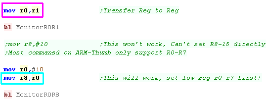
Thumb mode shares the same registers as regular ARM mode, however due to the reduction in the size of the commands, many of the commands only function with the so called "Low Registers" (R0-R7). There are a few commands which also work with the "High Registers".
The Stack Pointer, Link Register and Program Counter still have the same purpose as before.
|
Register |
Purpose |
|---|---|
|
R0 |
General |
|
R1 |
General |
|
R2 |
General |
|
R3 |
General |
|
R4 |
General |
|
R5 |
General |
|
R6 |
General |
|
R7 |
General |
|
R8 |
General |
|
R9 |
General |
|
R10 |
General |
|
R11 / FP |
Frame Pointer (Optional) |
|
R12 / IP |
Intra Procedural Call (Optional) |
|
R13 / SP |
Stack Pointer |
|
R14 / LR / LK |
Link Register |
|
R15 / PC |
Program Counter |
A "Frame pointer" points to data areas in the Stack, effectively
allocating a 'small stack allocation' for a subroutine. This frame pointer
register would be used with relative offsets. It's 'Suggested' R11 is used
for this purpose if you need it, it's entirely optional if you use R11 for
this or not.

|
We'll be
covering everything pretty completely in the ARM Thumb series, but
it will be assumed you know some ARM, Not particularly because the tutorials have anything 'missing' but because ARM can do more than THUMB, and ARM is the default CPU mode, so normal ARM is the more sensible place to start... check out the tutorial here. |
| We're going to be using VASM
as an assembler, it's a free which works on windows, OSX and
Linux My Devtools provide a batch file which will build the programs for you, but if you don't want to use them, the format of the build script is shown below:  -Fbin ... Specifies to create a Binary file -Dxxx=Y ... Specifies to define a symbol xxx=y (we'll learn about symbols later. -L ... Specifies a Listing file - this shows source code and resulting bytes... it's used for debugging if we have problems -o ... Specifies the output file. %BuildFile%... this would be the sourcefile you want to compile... Eg: Lesson1.asm -m7tdmi... (or equivalent) specifies the ARM architecture we're building for. -noialign... This will disable 32 bit alignment - we need this as each thumb command is 16 bit. -chklabels -nocase ... Disable case sensitivity, and check for lines where we've forgotten a tab on a command (it will be mistaken for a label) |
|
| Once we've successfully compiled our program, we can run it with
VisualBoyAdvance |
 |
| To allow us to get started programming quickly and see the
results, we'll be using a 'template program'...
(Thumb_Minimal.asm) This consists of 3 parts: A Generic Header - this will set up the screen and a few parameters we'll need to start. The Thumb switch... we need to use the BX (Branch and Xchange) command to turn on thumb mode... strangely, setting bit zero to 1 will turn on thumb mode after the branch! We then need a compiler directive .thumb to tell the assembler we're now using THUMB mode... We use .arm to re-enable normal ARM mode. The Program - this is the body of our program where we do our work. A Generic Footer - this gives us some support tools, and includes a common bitmap font. This template program will compile on any of the systems in these tutorials (RiscOS and the GameboyAdvance!) |
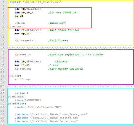 |
| There's a lot of
complex scary stuff in the include files - don't panic about
it for now, you'll be able to understand it more later once
you've covered all the lessons. |
 |
 |
BX exists in ARM and Thumb. It all comes down to Bit 0 - which can enable or disable Thumb mode. We can switch at any time to have a subroutine which is ARM, then another that is Thumb and so on! |
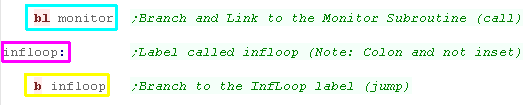
| Lets take a look at a simple program!... The first line is a command 'BL' (Branch and Link)... this is the same as CALL or JSR on other systems... it runs the subroutine labeled 'MemDump' - when that subroutine finishes (when register LR is transferred to PC) the program will carry on with the line after the BL call ... notice the command starts indented *this is required for commands* the next line is not indented and ends with a colon : - that makes it a label called 'infloop' ... labels tell the assembler to 'name' this position in the program - the assembler will convert the label to a byte number in the executable... thanks to the assembler we don't need to worry what number that ends up being... finally we have the command 'B' (Branch)... this is a jump! unlike BL (Branch and Link), it never returns... notice we're Branching to the label we just defined on the line before.... this makes the program run infinitely... a crude way to end our program so we can see the result! you'll also notice text in green starting with a Semicolon ; - this is a comment (REMark) - they have no effect on the code These are the same as the |
 |
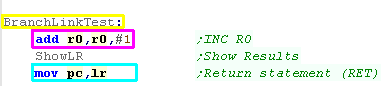
| Lets look at another subroutine. This one stars with a label 'BranchLinkTest'... we know it's a label because it's not indented and ends in a colon... this is the name of the subroutine - we'll see the name with BL (Branch and Link) statements (calls on the arm). Then there is an ADD Command... it adds 1 to r0 (R0=R0+1)... it is indented, so they are clearly commands... Finally there is a MOV PC,LR command - this ends a subroutine... BL transfers PC (the program counter... the current running byte) to LR - transferring LR back to PC returns to the command after the BL command if our code has a RET at the end - it's a subroutine and should probably be started with a CALL... if we start it with a JMP something bad will probably happen! |
 |
| Subroutines work the same
in ARM Thumb as they do in classic ARM, in the sense they use
the Link Register to contain the return address, and we have
to |
|
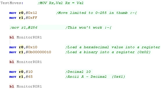
| Arm Thumb still supports Decimal,exadecimal and binary, but we
have some serious limitations now! We can only load immediate values between 0-255, we can't load 256 or more as an immediate or negative numbers. We can also only load the 'Low registers' R0-R7 directly in this way. |
 |
| Here's the result! | 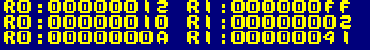 |
| We can transfer a register to a register, here we set
R0=R1 There is a version of this command which can transfer between low registers (R0-R7) and high registers (R8-R15)... it looks the same, but compiles to different bytes. |
 |
| R0 will be set to the value that was in R2 | 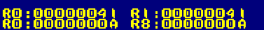 |
| If we want to load a larger value, or a negative value we can
use LDR. This will load a register from a 32 bit value in the code. Note in THUMB, the label must be AFTER the current line, and it can't be too far away |
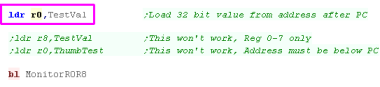  |
| This is how we can load numbers larger than 255, or negative numbers. | 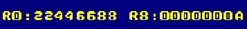 |
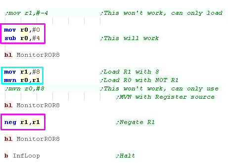
| We can't load other immediates in a single command, but we do
have a few options if we can use two commands! We can use MOV to load a zero value, then SUBtract an immediate (up to 255) to give an negative number we can use MVN (Move Not) to flip the bits of a register. We can use NEG to convert a positive number to a negative one. |
 |
| Here are the results | 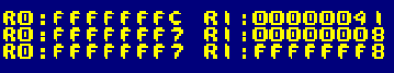 |
| Of course, we don't just have a MOVe command - we also have ADD
and SUB for addition and subtraction! There are two versions, a small immediate version which specifies a destination a source and an immediate up to 7, the second large immediate version specifies just the destination and a value to add or subtract Before we learned we could not load #0x12345678 directly into a register, however we can do this in two parts, loading the first 4 digits with MOV - then adding the other 4 with ADD |
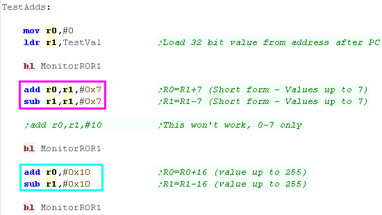 |
| the changes to the registers are shown here | 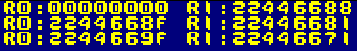 |
| We can also add registers to registers. If we're adding or subtracting low registers, we can specify two sources and a destination. If we're adding low and high registers, we only have a source and destination.... there's no subtract command! |
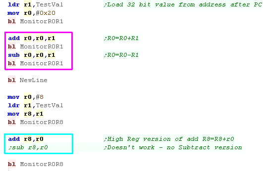 |
| Here are the results | 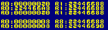 |
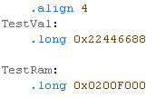
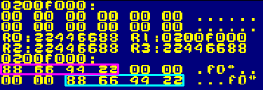
| We can load values in from ram with LDR, and store back with
STR. We can specify an offset... an offset of Zero just uses the register as the address, alternatively we can specify an offset, the source or destination will be the register plus the offset. |
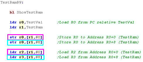  |
| Here are the results |
 |
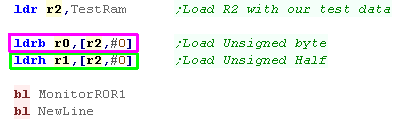
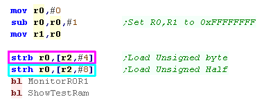
| LDR will load a 32 bit value, but we can load smaller values. LDRH will load a half (16 bit) LDRB will load a byte (8 bit) |
 |
| Here are the results |
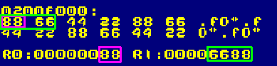 |
| We can also use STRB and STRH
to store bytes and Halves |
 |
| Here are the results of STRB and STRH | 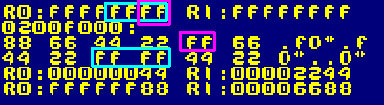 |
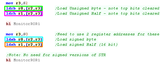
| If we want to use Bytes or Halves, we have two possible Load
options LDRB and LDRH will load unsigned bytes and halves. LDSB and LDSH will load signed bytes and halves. Signed loads will fill the unused bits with the top loaded bit, meaning the 32 bit register has the same signed value as the smaller loaded value. There is no signed store commands, there is no need for them. |
 |
| Here are the results of LDRB and LDRH
and LDSB and LDSH
|
 |
| The example here shows data is stored by the
ARM in 'Little Endian' format... meaning the lowest value byte
in a 32 bit register is stored first... and the highest is
stored last. This is basically always the case with the ARM - however the ARM CPU can actually also work in Big Endian mode. |
 |
| The previous LDR and STR worked with 32 bit registers... but
we'll often want to work with bytes, The ARM allows this with a LDRB and STRB command - they work the same as the other commands, but just load a single byte |
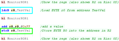 |
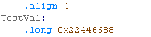
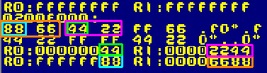
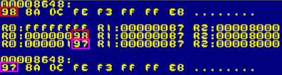
| We loaded in a byte from TestVal with
LDRB... Note that the 24 unused bits of the register changed to 0 We then added 255 - causing the R1 to expand out of a single byte... We then save back with STRB - because we used a byte command, only the low byte was saved |
 |
| LDR
and STR work with 32 bit values... LDRB and STRB work at 8
bit...But what about 16 bit? well LDRH and STRH (H=Half) will
load and save 16 bit... but these commands only exist on later processors, the Gameboy Advance uses them fine - but RiscOS can't use them! |
|
 |
Because
the ARM is 32 bit, a WORD is 32 bits on arm, rather than 16 bit
like on the Z80 or 68000 VASM uses the statement '.long' to define a 32 bit value - but a LONG on the ARM would typically be 64 bit. To avoid confusion the terms WORD and LONG won't be used in these tutorials - the length will be referred to in bits instead |
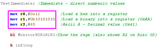
| We've already come across this!... Immediate addressing is where
the values are numbers stored directly in
the code In this example The value is transferred into the register. Immediates are for more limited with THUMB, for MOV the values can only be positive, and up to 255, but the limits vary depending on the command. |
 |
| The results are shown - our registers now contain the requested values | 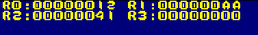 |
| Register addressing is far less exciting than it sounds... it's just where a parameter is taken from the value in a register. | 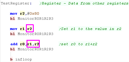 |
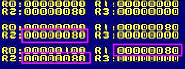
| Here we've set R1 to the value in R2, then R0 to the value of
R1+R2 These are both examples of register addressing |
 |
| Register Indirect is where the register holds an address, and
that address is the source of the value for the command.. With VASM in thumb mode, we need to specify an offset of #0 if we just want to use the register value. The register is wrapped in square brackets eg [r2,#0] |
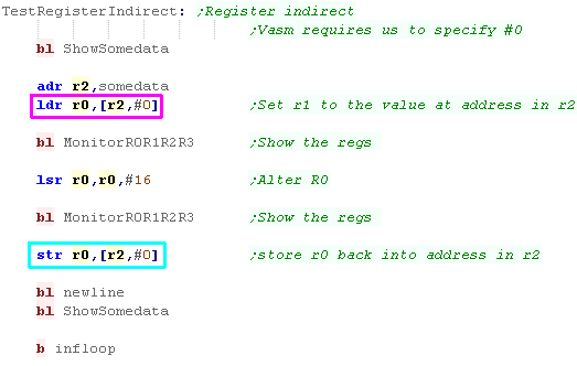 |
| We can load with LDR or save with STR
|
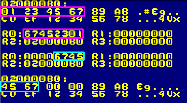 |
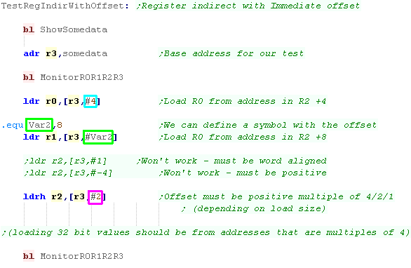
| As well as using the value of a register as the address, we can
use the register plus a fixed offset. the Offset is put in the square brackets [] after a comma To make things easier, we can define symbols and use those as the offset... The Offset must be a multiple of the amount loaded. In ARM Thumb, the offset cannot be negative. |
 |
| Here are the results | 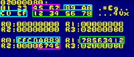 |
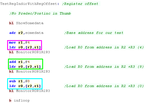
| Rather than a fixed offset from the address, we can use the
value in a register... effectively the resulting address is the
sum of the two addresses The resulting address must be correctly aligned for the size loaded. |
 |
| The registers will be loaded from their respective offsets. | 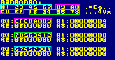 |
| ARM Thumb doesn't really have predecrement or
postincrement... you'll have to use an extra command to change the
register. There are, however PUSH and POP commands, and the LDMIA/STMIA command. |
 |
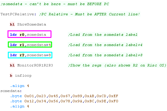
| There are some commands which use addresses nearby the current
code. We specify these with a label, our assembler will calculate
the offset. In many cases, the label must come AFTER the current line, and must be near the code using the offset. |
 |
| Here we've loaded the data from the offset. |
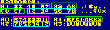 |
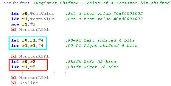
| Rather than being part of the other commands, LSL/LSR/ASR and
ROR are now stand alone commands. LSL and LSR can be used with the number of bits specified by an immediate. it can also be specified by a register. LSR and LSR are Logical Shift Left and Right... these halve or double unsigned numbers |
 |
| Here are the results | 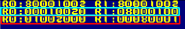 |
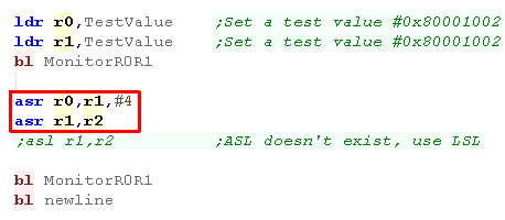
| We also have an ASR for shifting Signed
numbers right. Ther is no ASL... LSL can be used for shifting signed numbers left |
 |
| Here are the results | 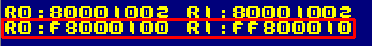 |
| Finally we have ROR - Rotate right. This cannot work with an immediate, also note there is no ROL, but rotating right 31 bits has the same effect as rotating left 1 bit |
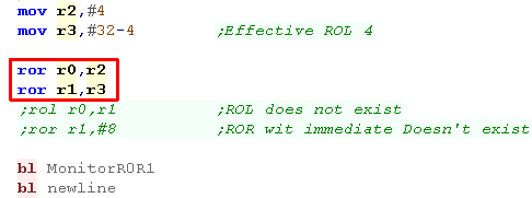 |
| Here is the result | 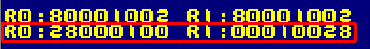 |
| While most of the previous range are no longer available, LDMIA
and STMIA are still usable on the
Thumb. As before, these allow multiple registers to be loaded from or stored to the address in another register, which is incremented after the command |
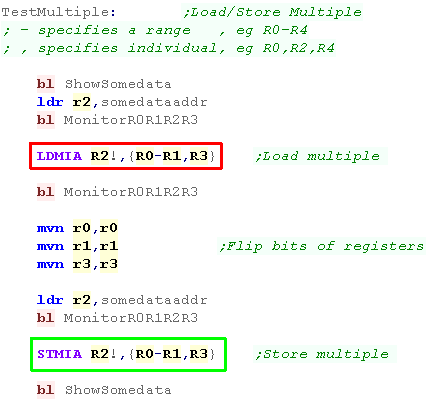 |
| Here we've loaded 3 values from R2 | 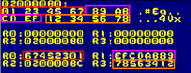 |
| Here we've stored 3 values to R2 | 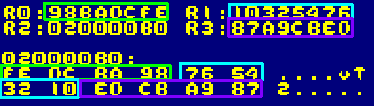 |
| Unlike the classic ARM, Thumb uses a dedicated Push and Pop command to back up and restore registers using the stack | 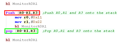 |
| Here are the results | 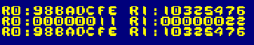 |
| There are far fewer
addressing options than the classic arm, but that's the price
you pay for halving the instruction length. Compared to 'Normal' ARM some commands will now take two or more, but overall your program will still end up smaller! |
|
| Flags in THUMB work very much the way they do on a Z80 or 68000,
Some commands set flags, other's don't. Unlike ARM we cannot select
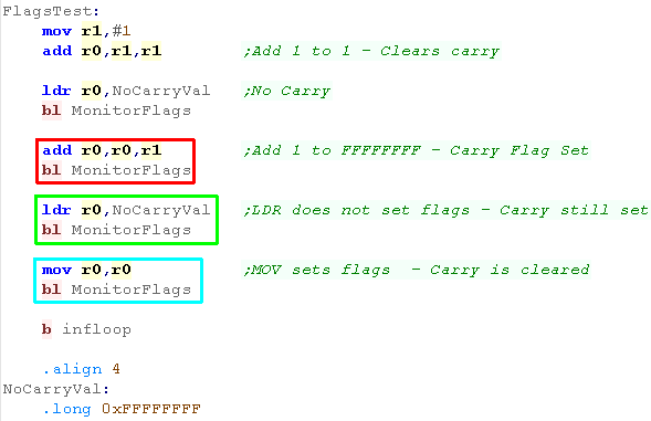
which commands change flags. Here we've used 3 commands, ADD and MOV change the flags. LDR does not. The only way you can know which change the flags is to check the documentation - or the ChibiAkumas Cheatsheet!. |
 |
| Here are the results | 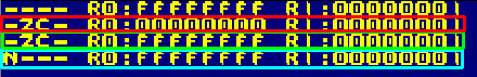 |
|
We're
going to look at some examples of these flags and condition
codes - but really you should try them yourselves! You'll notice commented out code (starting ;) - these are alternative tests you can do to see the conditions in action - Ideally you should try them yourselves, but they'll all be shown on the video! |
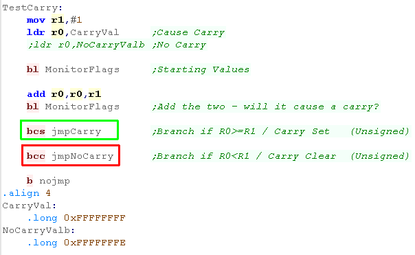
| The Carry flag is set when a register's value exceeds the limits
of 32 bit - for example when we add 1 to 0xFFFFFFFF, It will also be set by rotate commands that push a bit out of the register We're going to use a Branch command with a condition code to test for the carry... BCC will Branch if Carry is Clear... BCS will branch if Carry is Set BCS = Carry Set BCC = Carry Clear |
 |
| The Carry flag was set, so the BCS occurred, showing a C to the screen | 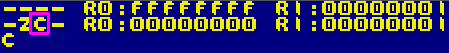 |
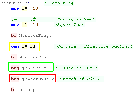
| The Zero flag is set whenever a mathematical operation results
in zero - either because of a subtraction, an addition or
overflows, or other operation that results in a register
containing zero... it's also set when a compare operation is
performed on two registers with the same value - as the difference
is zero. CMP sets the flags the same as a SUB command would, but doesn't change the registers We'll use BEQ (Branch if Equals) and BNE (Branch if Not Equals) BEQ - Equals (Zero) BNE - Not Equals (Not Zero) |
 |
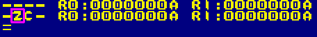
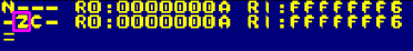
| The Zero flag was set (because the
difference between the two registers was zero) This caused the jump to occur, and the = was shown. |
 |
| CMP sets the flags the same as SUB, but the alternative is
Compare Negative... CMN sets the flags the same as a ADD command would, but doesn't change the registers |
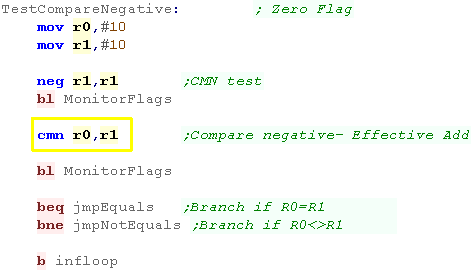 |
| The Zero flag was set (because the
difference between the two registers was zero) This caused the jump to occur, and the = was shown. |
 |
| Unsigned mathematics (that do not use negative numbers ) use 4
comparisons - two we've already seen! the CMP command is effects the flags like a 'subtraction' command, but does not alter registers. there are four commands >= BCS - Carry Set < BCC - Carry Clear > BHI - Higher (Carry set and Zero Clear) <= BLS - Lower or same (Carry Clear or Zero Set) Because negative numbers start with a 1 as the top bit, they will be treated as very large by these commands, we need to use other commands to test these |
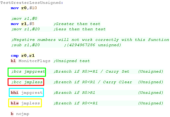 |
| The Zero and Carry flag will be set
depending on the values compared |

|
| Because of the way negative numbers works in assembly, We need
to use 4 different commands for comparing signed numbers, there are four commands >= BGE - Greater or Equals (N set and V set or N clear and V clear) < BLT- Less Than (N set and V clear or N clear and V set) > BGT - Greater Than (Z clear and N set or V set or N clear and V clear) <= BLE - Less than or Equals (Z set or N set and V clear, or N clear and V set) |
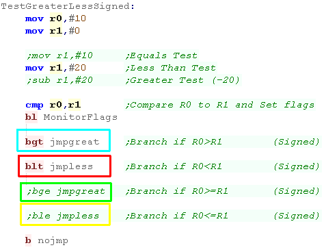 |
| The jumps will occur according to the flags... the flag-rules are pretty complex for these, but the commands are easy to use. |  |
| There may be times we need to simply know if a number is
positive or negative, the N flag does this for us... We can use two special conditions to do this BPL - Positive (Negative Clear BMI - Minus (Negative set) |
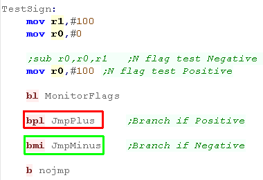 |
| The N flag is set according to the top bit of the register |  |
| Overflow occurs when the limit of a signed number is breached
and a positive number incorrectly flips to a negative (or vice
versa) A signed number cannot contain >+32767 or <-32768... when it tries to the top bit will flip, and the value will become invalid... Overflow is designed to allow this to be detected... we have two conditions: BVS - oVerflow Set BVC - oVerflow Clear |
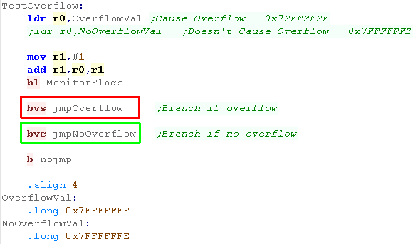 |
| The jump will occur according to the V flag |  |
| Lesson
4
- The Stack... and SWI The Stack in Thumb works basically the same as ARM, but now we have a 'proper' PUSH and POP command... lets recap stack usage, and learn about them. |
 |
 Thumb_Lesson4.asm |
 |
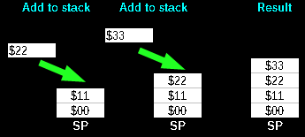
| 'Stacks' in assembly are like an
'In tray' for temporary storage... Imagine we have an In-Tray... we can put items in it, but only ever take the top item off... we can store lots of paper - but have to take it off in the same order we put it on!... this is what a stack does! If we want to temporarily store a register - we can put it's value on the top of the stack... but we have to take them off in the same order... The stack will appear in memory, and the stack pointer goes DOWN with each push on the stack... so if it starts at $2000 and we push 2 bytes, it will point to $1FFE As the ARM is 32 bit, we'll push onto the stack 32 bits at a time. |
  |
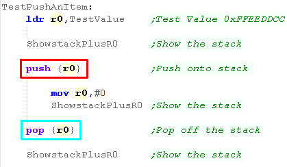
| PUSH and POP
use the SP register to back up and restore values using
the stack... the amount pushed is always 32 bit, and multiple
registers can be specified like LDMIA and STMIA In this example, we'll load R0 with a value, push it onto the stack, change R0, then restore the pushed value from the stack We'll view the registers and stack at each stage |
 |
| The test value was loaded into R0 - Pushed onto the stack... then Popped into R0 | 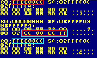 |
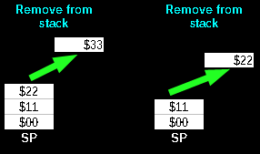
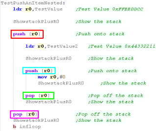
| We can nest pushes... The important thing to understand is that
we pop off in the reverse order to the way we pushed them on... We can also push a value in R0 onto the stack, and pop it off in R1 |
 |
| The two values are pushed onto an popped off the stack | 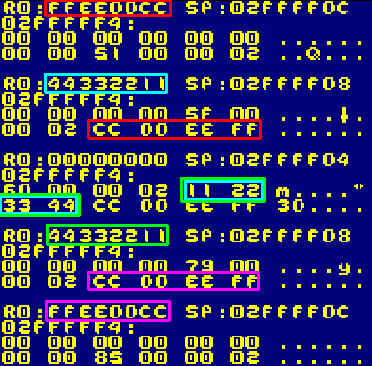 |
| We can push multiple items. We can specify a range with "-"... eg (R1-R3) We can specify a range with ","... eg (R1,R2,R3) The order of the registers doesn't matter, (R1,R2) and (R2,R1) have the same result |
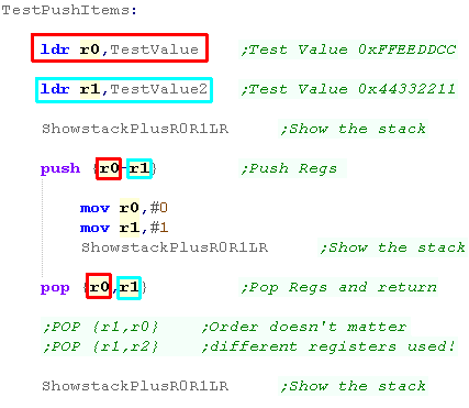 |
| in this case R0 and R1 were pushed onto, and popped off the stack | 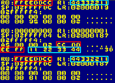 |
| We can transfer multiple registers to a destination with STMIA
and LDMIA, With these, as with Push/Pop We use a comma list eg (r1,r2,r4) and/or a range (r1-r4,r6) The order we put the registers in the list doesn't affect the order they are transferred But of course if we pop them of into different registers, things could go wrong! |
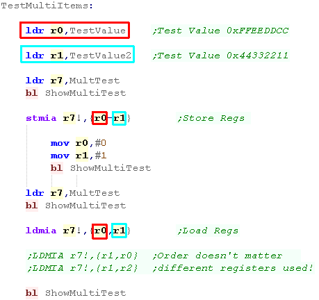 |
| The items will be pushed onto the stack and popped off in one go! | 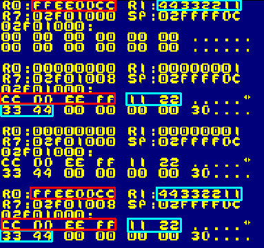 |
| As we learned, Branch and Link moves the Program (PC) counter
into the Link Register (LR) When we perform a RETurn, the assembler actually creates a MOV PC,LR command... Because we need the LR to be intact to return, we need to back it up somehow if we're nesting subroutines... The easiest solution is to push it onto the stack, and pop it back into the PC... Alternatively, we could transfer it into another register |
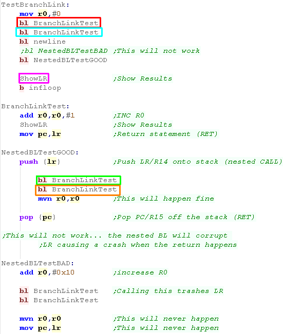 |
| Here is the changes to the stack and Link Register | 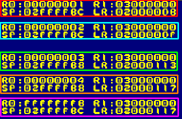 |
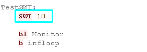
| SWI stands for SoftWare Interrupt... Like the RST's of the Z80 and the TRAPs of the 68000 these are often used for OS calls...On RiscOS there are a variety of SWI's... To use a SWI we use the commands followed by a byte value... What the SWI does and what parameters need to be passed will depend on the system, you'll need to consult the documentation of that system for details. |
 |
 |
If
you're programming the Gameboy Advance or NDS then you'll
probably never need SWI... these tutorials use the firmware as
little as possible, so you won't see it much in those
either... If you're using the firmware though, you'll have to check the manual for Risc-OS, and beware! there are different versions for later Risc OS versions! |
| Lesson
5
- More Maths! We're nearly done... but we need to look at operations that work at the bit level, and a few other important commands... lets take a look! |
|
Thumb_Lesson5.asm |
|
| We have four kinds of logical operations we can perform
on bits. In thumb mode, These take two parameters, the destination on the left, the unchanged parameter on the right. AND = Return 1 where both parameters are 1 - else 0 ORR = (or) Return 1 where either parameter is 1 - else 0 EOR = Flip bits in first parameter where second parameter is 1 BIC = (Bit CLear) Zero bits in first parameter when second parameter is 1 |
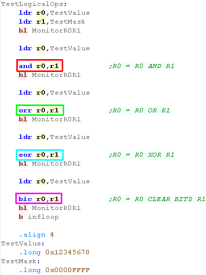 |
| The results are shown here | 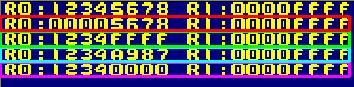 |
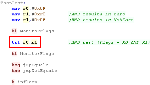
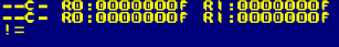
Test Operations TST
| Testing sets the flags like an AND, but does not alter the
registers TST = effectively ANDs the two perimeters setting the flags accordingly |
 |
| Here is the result! |
 |
| There may be times when even
32 bit isn't enough - when we do ADDition or SUBtraction that goes
over the limit of a 32 bit register, we can use special commands to
add that carry to a second register - the two registers together
will give us 64 bits! ADC adds a parameter + any carry to the top register. SBC Subtracts a parameter and any carry to the top register. |
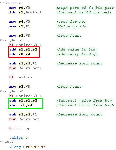 |
| Here are the results, when the bottom byte over/under flowed, the top byte was altered to compensate for the carry/borrow |  |
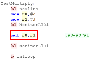
Multiplication
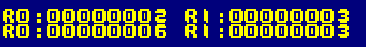
| Arm Thumb offers a single multiplication command MUL - MUltiplies two parameters together... in this case R0=R0*R1 (R1 is unchanged) |
 |
| The result of the two operation is shown here 3*2=6 |
 |
| We've covered pretty much all
the ARM thumb commands... so if you need something you've not seen
you've got two choices... simulate it with the Thumb commands, or
use BX to switch back to full ARM mode, and use the command there! For example the MRS command to get the flags doesn't exist in ARM Thumb, but this tutorial needed it, a BX to full arm mode was the solution! |
|
| View Options |
| Default Dark |
| Simple (Hide this menu) |
| Print Mode (white background) |
| Top Menu |
| ***Main Menu*** |
| Youtube channel |
| Patreon |
| Introduction to Assembly (Basics for absolute beginners) |
| Amazon Affiliate Link |
| AkuSprite Editor |
| ChibiTracker |
| Dec/Bin/Hex/Oct/Ascii Table |
| Alt Tech |
| Archive.org |
| Bitchute |
| Odysee |
| Rumble |
| DailyMotion |
| Please note: I wlll upload more content to these alt platforms based on the views they bring in |
| 68000 Content |
| ***68000 Tutorial List*** |
Learn 68000 Assembly  |
| Hello World Series |
| Platform Specific Series |
| Simple Samples |
| Grime 68000 |
| 68000 Downloads |
| 68000 Cheatsheet |
| Sources.7z |
| DevTools kit |
| 68000 Platforms |
| Amiga 500 |
| Atari ST |
| Neo Geo |
| Sega Genesis / Mega Drive |
| Sinclair QL |
| X68000 (Sharp x68k) |
| 8086 Content |
| Learn 8086 Assembly |
| Platform Specific Series |
| Hello World Series |
| Simple Samples |
| 8086 Downloads |
| 8086 Cheatsheet |
| Sources.7z |
| DevTools kit |
| 8086 Platforms |
| Wonderswan |
| MsDos |
| ARM Content |
| Learn ARM Assembly |
| Learn ARM Thumb Assembly |
| Platform Specific Series |
| Hello World |
| Simple Samples |
| ARM Downloads |
| ARM Cheatsheet |
| Sources.7z |
| DevTools kit |
| ARM Platforms |
| Gameboy Advance |
| Nintendo DS |
| Risc Os |
| Risc-V Content |
| Learn Risc-V Assembly |
| Risc-V Downloads |
| Risc-V Cheatsheet |
| Sources.7z |
| DevTools kit |
| MIPS Content |
| Learn Risc-V Assembly |
| Platform Specific Series |
| Hello World |
| Simple Samples |
| MIPS Downloads |
| MIPS Cheatsheet |
| Sources.7z |
| DevTools kit |
| MIPS Platforms |
| Playstation |
| N64 |
| PDP-11 Content |
| Learn PDP-11 Assembly |
| Platform Specific Series |
| Simple Samples |
| PDP-11 Downloads |
| PDP-11 Cheatsheet |
| Sources.7z |
| DevTools kit |
| PDP-11 Platforms |
| PDP-11 |
| UKNC |
| TMS9900 Content |
| Learn TMS9900 Assembly |
| Platform Specific Series |
| Hello World |
| TMS9900 Downloads |
| TMS9900 Cheatsheet |
| Sources.7z |
| DevTools kit |
| TMS9900 Platforms |
| Ti 99 |
| 6809 Content |
| Learn 6809 Assembly |
| Learn 6309 Assembly |
| Platform Specific Series |
| Hello World Series |
| Simple Samples |
| 6809 Downloads |
| 6809/6309 Cheatsheet |
| Sources.7z |
| DevTools kit |
| 6809 Platforms |
| Dragon 32/Tandy Coco |
| Fujitsu FM7 |
| TRS-80 Coco 3 |
| Vectrex |
| 65816 Content |
| Learn 65816 Assembly |
| Hello World |
| Simple Samples |
| 65816 Downloads |
| 65816 Cheatsheet |
| Sources.7z |
| DevTools kit |
| 65816 Platforms |
| SNES |
| eZ80 Content |
| Learn eZ80 Assembly |
| Platform Specific Series |
| eZ80 Downloads |
| eZ80 Cheatsheet |
| Sources.7z |
| DevTools kit |
| eZ80 Platforms |
| Ti84 PCE |
| IBM370 Content |
| Learn IBM370 Assembly |
| Simple Samples |
| IBM370 Downloads |
| IBM370 Cheatsheet |
| Sources.7z |
| DevTools kit |
| Super-H Content |
| Learn SH2 Assembly |
| Hello World Series |
| Simple Samples |
| SH2 Downloads |
| SH2 Cheatsheet |
| Sources.7z |
| DevTools kit |
| SH2 Platforms |
| 32x |
| Saturn |
| PowerPC Content |
| Learn PowerPC Assembly |
| Hello World Series |
| Simple Samples |
| PowerPC Downloads |
| PowerPC Cheatsheet |
| Sources.7z |
| DevTools kit |
| PowerPC Platforms |
| Gamecube |
| Work in Progress |
| ChibiAndroids |
| Misc bits |
| Ruby programming |
Buy my Assembly programming book
on Amazon in Print or Kindle!

Available worldwide!
Search 'ChibiAkumas' on
your local Amazon website!
Click here for more info!

Buy my Assembly programming book
on Amazon in Print or Kindle!
Available worldwide!
Search 'ChibiAkumas' on
your local Amazon website!
Click here for more info!
Buy my Assembly programming book
on Amazon in Print or Kindle!
Available worldwide!
Search 'ChibiAkumas' on
your local Amazon website!
Click here for more info!