

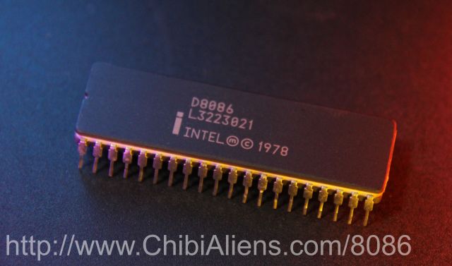
These tutorials focus on the 8086, but also discuss the 186 and later x86 cpus
| The 8086 was the successor to the
8080, from beginnings similar to the Z80, the 8086 was designed to
set a foot into the 16 bit world! In a 40 pin form and with segments to allow it to break out of the limits of a 16 bit address bus, the 8086 was the competitor to the 68000.... and while inferior in some ways - it was set to dominate the computing industry, blasting all it's rivals away, killing mighty giants like the PowerPC, the Sony CELL and even the ITANIUM! - only the highly efficient ARM processor today has managed to stand up to it's power! Lets take a look at the beginnings of the 8086, and we'll also look a little at what was added to this chip, in the modern systems we use today! In these tutorials we'll be looking at MS-DOS based IBM PC's and the WonderSwan |
 |
 |
 |
If you want to learn 8086 get the Cheatsheet! it has all the 8086 commands, It will help you get started with ASM programming, and let you quickly look up commands when you get confused! |  |
 |
We'll
be
using USAM as our assembler for these tutorials You can get the source and documentation for UASM from the official website HERE |
Resources
8086 reference manual - Detailed but to the point reference manual
MASM programimng guide - We use UASM, but it's MASM compatible!
UASM - the x86 assembler used by these tutorials (free and open source!)
Platforms covered in this series
MS-Dos based IBM PC
Wonderswan / Wonderswan Color
ChibiAkumas Tutorials
Absolute Beginners series (Terminology and concepts)
8086 Multiplatform Lessons
| Lesson M1 - Random Numbers and Ranges [DOS] |
| Lesson M2 - Binary Coded Decimal |
8086 Hello World Series
| Lesson H1 - Hello World on MS Dos |
| Lesson H2 - Hello World on the WonderSwan / Wonderswan Color |
| Lesson H3 - Hello World on MS Dos via Native Tools (MASM 6.11) [DOS] |
8086 Simple Samples
| Lesson S1 - Sprite drawing and Simple key movement in MS DOS |
| Lesson S2 - Sprite drawing and Simple key movement on the Wonderswan |
8086 Platform Specific Lessons
8086 SuckHunt Series
What is the 8086 and what are 16 'bits' You can skip this if you know about binary and Hex (This is a copy of the same section in the Z80 tutorial)
The 8086 is an 16-Bit processor with a 20 bit Address bus... though actually the Address bus and Data bus share the same pins on the CPU!
The 8088 is the same as the 8086, but it only has an 8 bit data bus... this makes it slower, but it makes no difference to our programs!
What's this 'bit'... well, one 'Bit' can be 1 or 0
four bits make a Nibble (0-15)
two nibbles (8 bits) make a byte (0-255)
two bytes (16 bits) make a word (0-65535)
And what is 65535? well that's 64 kilobytes ... in computers Kilo is 1024, because 2^10 = 1024
 |
The
8086 is pretty old now, but it's the basis of all the
computers we have today... With the 8086, We can learn about the fundamentals of computing and we can have some fun along the way! |
Numbers in Assembly can be represented in different ways.
A 'Nibble' (half a byte) can be represented as Binary (0000-1111) , Decimal (0-15) or Hexadecimal (0-F)... unfortunately, you'll need to learn all three for programming!
Also a letter can be a number... Capital 'A' is stored in the computer as number 65!
Think of Hexadecimal as being the number system invented by someone wit h 15 fingers, ABCDEF are just numbers above 9!
Decimal is just the same, it only has 1 and 0.
In this guide, Binary will shown with a b at the end... eg 11001100b ...
Hexadecimal will be shown with h
at the end, however the value MUST start with a number (0-9) not a letter
(A-F), so we may have to add a 0 to the start eg.. 0FFh... it's also possible to specify FFh as 0xFF
| Base |
Type |
symbol |
Alternate |
| 2 | Binary |
10101010b | |
| 8 | Octal |
777o | 777q |
| 10 | Decimal |
100 | 100d |
| 16 | Hex |
0FFh | 0xFF |
| The
symbols used to denote numbers vary between assemblers, in
these 8086 tutorials we use UASM, and --h is used for
hexadecimal, eg 0FFh, and ---b for binary, eg 1010b If your not using UASM, you many need something different! |
 |
| Decimal | 0 | 1 | 2 | 3 | 4 | 5 | 6 | 7 | 8 | 9 | 10 | 11 | 12 | 13 | 14 | 15 | ... | 255 |
| Binary | 0000 | 0001 | 0010 | 0011 | 0100 | 0101 | 0110 | 0111 | 1000 | 1001 | 1010 | 1011 | 1100 | 1101 | 1110 | 1111 | 11111111 | |
| Hexadecimal | 0 | 1 | 2 | 3 | 4 | 5 | 6 | 7 | 8 | 9 | A | B | C | D | E | F | FF |
Another way to think of binary is think what each digit is 'Worth' ... each digit in a number has it's own value... lets take a look at %11001100 in detail and add up it's total
| Bit position | 7 | 6 | 5 | 4 | 3 | 2 | 1 | 0 |
| Digit Value (D) | 128 | 64 | 32 | 16 | 8 | 4 | 2 | 1 |
| Our number (N) | 1 | 1 | 0 | 0 | 1 | 1 | 0 | 0 |
| D x N | 128 | 64 | 0 | 0 | 8 | 4 | 0 | 0 |
| 128+64+8+4= 204 So %11001100 = 204 ! | ||||||||
If a binary number is small, it may be shown as %11 ... this is the same as %00000011
Also notice in the chart above, each bit has a number, the bit on the far right is no 0, and the far left is 7... don't worry about it now, but you will need it one day!
| If your maths sucks and you
can't figure it out, look at Windows Calculator, Switch to
'Programmer Mode' and it has binary and Hexadecimal view,
so you can change numbers from one form to another! If you're an Excel fan, Look up the functions DEC2BIN and DEC2HEX... Excel has all the commands to you need to convert one thing to the other! |
 |
But wait! I said a Byte could go from 0-255 before, well what happens if you add 1 to 255? Well it overflows, and goes back to 0!... The same happens if we add 2 to 254... if we add 2 to 255, we will end up with 1
this is actually useful, as if we want to subtract a number, we can use this to work out what number to add to get the effect we want
| Negative number | -1 | -2 | -3 | -5 | -10 | -20 | -50 | -254 | -255 |
| Equivalent Byte value | 255 | 254 | 253 | 251 | 246 | 236 | 206 | 2 | 1 |
| Equivalent Hex Byte Value | FF | FE | FD | FB | F6 | EC | CE | 2 | 1 |
 |
All these number types can
be confusing, but don't worry! Your Assembler will do the work
for you! You can type 0b11111111 , 0xFF , 255 or -1 ... but the assembler knows these are all the same thing! Type whatever you prefer in your ode and the assembler will work out what that means and put the right data in the compiled code! |
The 8086 Registers
The 8086 is similar to the Z80's registers, but we've got some added stuff to handle the 1MB memory capability!
Registers in the 8086 are all 16 bit... but AX,BX,CX and DX can be split into 2 8 bit parts, called AH and AL, BH and BL and so on!
Main
Registers:
String commands Copy DS:SI to ES:DI Segment Registers:
The Registers are 16 bit, but the address bus is 20 bit... these 'Segment registers' are added to the top 20 bits of the address eg: ----DDDDDDDDDDDDDDDD ... D=DX EEEEEEEEEEEEEEEE---- ... E=ES |
Flags: ----ODIT
SZ-A-P-C
|
|||||||||||||||||||||||||||||||||||||||||||||||||||||||||||||||||||||||||||||||||||||||||||||||||||||
The 386 extended the all these registers to
32 bits.... the 32 bit versions have an E at the start, so EAX,EBX,ECX,
EDX... and EBP,ESP,ESI,EDI... also more data segments were added,
after DS and ES, we have FS and GS
Later machines like the Pentium III and x64 added more registers... but we're not covering them here!
Special Memory addresses on the 8086
Later machines like the Pentium III and x64 added more registers... but we're not covering them here!
Special Memory addresses on the 8086
| There are some special addressing ranges you'll want to know about... |
|
Interrupt Addresses
Addresses 0000:0000h - 0000:007Fh are
Interrupt pointers for INT 00h-31h
| Interrupt | From | Purpose |
| 0 - Div0 | 0000/1 | IP - Offset |
| 0002/3 | CS - Segment | |
| 1 - Step Trap | 0004/5 | IP - Offset |
| 0006/7 | CS - Segment | |
| 2 - NMI | 0008/9 | IP - Offset |
| 000A/B | CS - Segment | |
| 3 - 1 byte INT | 000C/D | IP - Offset |
| 000E/F | CS - Segment | |
| 4
- Sign Overflow |
0010/1 | IP - Offset |
| 0012/3 | CS - Segment | |
| 5 - reserved | 0014/5 | IP - Offset |
| 0016/7 | CS - Segment | |
| reserved | ... | ... |
| 31 -reserved | 007C/D | IP - Offset |
| 007E/F | CS - Segment |
The 8086 Addressing Modes
| Mode | Description | Sample Command | Valid Registers |
| Register Addressing | An 8 or 16 bit register | mov ax,bx mov al,bl |
- |
| Immediate Addressing | A constant value | mov ax,100 | |
| Direct Memory Addressing | A fixed location in memory | mov ax,[1000h] INC BYTE PTR [MyData] |
We may need to specifiy WORD PTR [label] |
| Register indirect Addressing | Contents of register used as an address | mov ax,[bx] | [BX], [BP], [DI], [SI] |
| Based or Indexed Addressing | Contents of register (Base or Index) plus displacement | mov ax,[bx+4] | d+[BX], d+[BP], d+[DI], d+[SI] |
| Based, Indexed Addressing | Contents of base register plus contents of index register | mov ax, [bx+di] mov ax, [bx+si] mov ax, [bp+di] mov ax, [bp+si] |
[BX][DI], [BX][SI], [BP][DI], [BP][SI] |
| Based, Indexed Addressing with displacement | Sum of base register, index register, and displacement | mov ax, table[bx][di] mov ax, table[di][bx] mov ax, table[bx+di] mov ax, [table+bx+di] mov ax, [bx][di]+table |
d+[BX][DI], d+[BX][SI], d+[BP][DI], d+[BP][SI] |
| String Addressing | String commands. | MOVSB MOVSW |
Src = DS:SI Dest = ES:DI |
Reading from memory addresses by label
| If we want to read from an address specified by label we must
specify the size of the data we want to read from the address...
there are 3 commands we can use: BYTE PTR - Load a byte WORD PTR - Load a Word DWORD PTR - Load a DoubleWord (386+) |
SomeData: dw 1234h ;2 bytes of data mov ax,WORD PTR [cs:somedata] ;This will work mov ax,[cs:008Ch] ; if somedata=008Ch this will work mov ax,[cs:somedata] ;This will NOT work |
Useful commands
| Set Trap Flag | Command to set trap flag (preserves other flags) | pushf mov bp,sp or word ptr [bp],0100h ; Set Trap flag (T) popf |
| Set Trap Flag Quick | Command to set trap flag | mov ax,0100h
;Clear the trap flag (T) push ax popf |
| Clear Trap Flag | Command to clear trap flag (preserves other flags) | popf mov bp,sp and word ptr [bp],0FEFFh ; Clear Trap flag (T) popf |
| Clear Trap Flag Quick | Command to clear trap flag | mov ax,0000h
;Clear the trap flag push ax popf |
Reserving data
RESB 1 allocates 1 byte.
RESW 1 allocates 2 bytes.
RESD 1 allocates 4 bytes.
RESQ 1 allocates 8 bytes.
Data Definitions
BYTE, DB (byte) Allocates unsigned numbers from 0 to 255.
SBYTE (signed byte) Allocates signed numbers from �128 to +127.
WORD, DW (word = 2 bytes) Allocates unsigned numbers from 0 to 65,535 (64K).
SWORD (signed word) Allocates signed numbers from �32,768 to +32,767.
DWORD, DD (doubleword = 4 bytes), Allocates unsigned numbers from 0 to 4,294,967,295 (4 megabytes).
SDWORD (signed doubleword) Allocates signed numbers from �2,147,483,648 to +2,147,483,647.
FWORD, DF (farword = 6 bytes) Allocates 6-byte (48-bit) integers. These values are normally used only as pointer variables on the 80386/486 processors.
QWORD, DQ (quadword = 8 bytes) Allocates 8-byte integers used with 8087-family coprocessor instructions.
TBYTE, DT (10 bytes), Allocates 10-byte (80-bit) integers if the initializer has a radix specifying the base of the number.
Defining areas of data (Like DS in Z80)
BYTE 256 DUP (0) - define 256 bytes all zero
you can use
Default Segments
mov ax, nearvar ; Reads from DS:[nearvar]
mov di, [bx] ; Reads from DS:[bx]
mov [di], cx ; Writes to DS:[di]
mov [bp+6], ax ; Writes to SS:[bp+6]
mov bx, [bp] ; Reads from SS:[bp]
MASM Data Types
RESW 1 allocates 2 bytes.
RESD 1 allocates 4 bytes.
RESQ 1 allocates 8 bytes.
Data Definitions
| Bytes | Z80 | 68000 | 8086 | ARM |
| 1 |
DB | DC.B | DB | .BYTE |
| 2 |
DW | DC.W | DW | .WORD |
| 4 |
DC.L | DD | .LONG | |
| n |
DS | DS | DUP | .SPACE |
BYTE, DB (byte) Allocates unsigned numbers from 0 to 255.
SBYTE (signed byte) Allocates signed numbers from �128 to +127.
WORD, DW (word = 2 bytes) Allocates unsigned numbers from 0 to 65,535 (64K).
SWORD (signed word) Allocates signed numbers from �32,768 to +32,767.
DWORD, DD (doubleword = 4 bytes), Allocates unsigned numbers from 0 to 4,294,967,295 (4 megabytes).
SDWORD (signed doubleword) Allocates signed numbers from �2,147,483,648 to +2,147,483,647.
FWORD, DF (farword = 6 bytes) Allocates 6-byte (48-bit) integers. These values are normally used only as pointer variables on the 80386/486 processors.
QWORD, DQ (quadword = 8 bytes) Allocates 8-byte integers used with 8087-family coprocessor instructions.
TBYTE, DT (10 bytes), Allocates 10-byte (80-bit) integers if the initializer has a radix specifying the base of the number.
Defining areas of data (Like DS in Z80)
BYTE 256 DUP (0) - define 256 bytes all zero
you can use
Default Segments
mov ax, nearvar ; Reads from DS:[nearvar]
mov di, [bx] ; Reads from DS:[bx]
mov [di], cx ; Writes to DS:[di]
mov [bp+6], ax ; Writes to SS:[bp+6]
mov bx, [bp] ; Reads from SS:[bp]
MASM Data Types
| Type | Defined by | Example |
| Hexadecimal | 0x | #0xFF |
| Deximal | #255 | |
| Binary | 0b | #0b11110000 |


Our Compiler and emulator
| We're going to be using UASM
as an assembler, it's a free Microsoft MASM assembler which
works on windows, OSX and Linux My Devtools provide a batch file which will build the programs for you, but if you don't want to use them, the format of the build script is shown below:  -mz ... Specifies to create DOS EXE File -Dxxx=Y ... Specifies to define a symbol xxx=y (we'll learn about symbols later. -Fl ... Specifies a Listing file - this shows source code and resulting bytes... it's used for debugging if we have problems -Fo ... Specifies the output file. %BuildFile%... this would be the sourcefile you want to compile... Eg: Lesson1.asm |
|
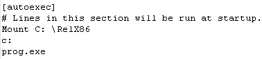
| Once we've successfully compiled our program, we'll run it with
DOSBOX If we want the program to start automatically we'll need to add a few extra lines to the dosbox.conf |
 |
A template program
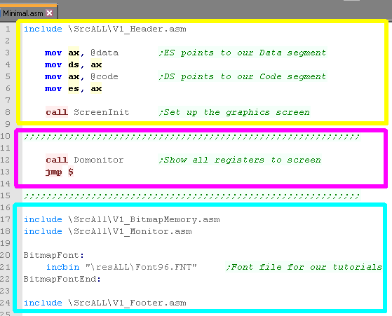
| To allow us to get started programming quickly and see the
results, we'll be using a 'template program'... This consists of 3 parts: A Generic Header - this will set up the screen and a few parameters we'll need to start. The Program - this is the body of our program where we do our work. A Generic Footer - this gives us some support tools, and includes a common bitmap font. This template program will compile on any of the systems in these tutorials (DOS and the WonderSwan!) |
 |
| There's a lot of
complex scary stuff in the include files - don't panic about it
for now, you'll be able to understand it more later once you've
covered all the lessons. |
 |
Commands, Labels and Calls
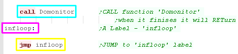
| Lets take a look at a simple program!... The first line is a command 'CALL'... this runs the subroutine labeled 'DoMonitor' - when that subroutine finishes (with a RET command) the program will carry on with the line after the call... notice the command starts indented *this is required for commands* the next line is not indented and ends with a colon : - that makes it a label called 'infloop' ... labels tell the assembler to 'name' this position in the program - the assembler will convert the label to a byte number in the executable... thanks to the assembler we don't need to worry what number that ends up being... finally we have the command 'JMP'... a jump! unlike a call, it never returns... notice we're jumping to the label we just defined on the line before.... this makes the program run infinitely... a crude way to end our program so we can see the result! you'll also notice text in green starting with a Semicolon ; - this is a comment (REMark) - they have no effect on the code |
 |
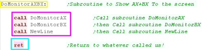
Subroutines and returns
| Lets look at another subroutine. This one stars with a label 'DoMonitorAXBX'... we know it's a label because it's not indented and ends in a colon... this is the name of the subroutine - we'll see the name with call statements. Then there are 3 Calls... these are indented, so they are clearly commands... because Calls return after running, first subroutine 'DoMonitorAX' will occur, then 'DoMonitorBX', then 'Newline' Finally there is a RET command - this ends a subroutine... RETurning back to the CALL statement that started it. if our code has a RET at the end - it's a subroutine and should probably be started with a CALL... if we start it with a JMP something bad will probably happen! |
|
| There may be times you see
code do weird things with CALL,JMP and RET statements that
aren't as simple as this... Don't worry about it for now - It's to complex for you right now... but don't worry, soon you to will be able to wield awesome ASM power! |
|
16 bit Registers, and 8 bit parts
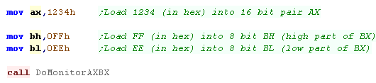
| It's time to start loading
data into 'registers'... Registers are the small bits of memory in the processor we use to store values we want to perform calculations on... AX is a 16 bit register... we can load it with two bytes (one word) '1234h' with the MOVe command... The AX on the left is the destination of the command. the 1234h on the right is the source 1234h is MOVed into the register AX finally we call DoMonitorAX - it will show the result to the screen. |
 |
| Here's the result |  |
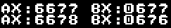
| 16 bit register AX is made up of two bytes... a High byte and a Low byte... we can use AX as two 8 bit registers called AH and AL... we can MOVe single byte values into these in the same way. | 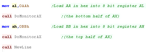 |
| First we changed the low part (AL) then the high part (AH)... the two parts of AX are changed accordingly. |  |
|
AX
isn't the only register we can do this with... we also have
BX,CX and DX... There's other registers like DI and SI - but these can't be split into 8 bit parts - they are for 'special purposes' |
Hex,Dec,Binary and Asc Oh my!...
also Adding and Subtracting.
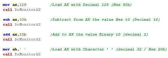
| We've been using Hexadecimal up until now... Hexadecimal
is pretty much the 'standard' for ASM programming on the x86
- but it's not to friendly for humans!... the H at the end of 1234h told the assembler it was a HEX number... If we take the H off it would be treated as a Decimal number... There's times we'll want to use Binary - by putting a B on the end - or Ascii (etters) by putting things in single quotes ' ' In this example we'll load AX with 128 in decimal... Well then use some new commands SUB and ADD... these will SUBtract and ADD a value to AX... we'll see the result after each command. Finally we'll load an ascii character into AL.. the assembler convert it to the number code for that character. |
 |
| Here is the result |  |
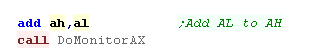
| Of course... we don't just have to do these commands with
'fixed' values (immediate), we can use the value of one register
on the value of another... For example we can add 8 bit part AL to AH |
 |
| Here's the result... AH has gone from 20h to 92h (+72h) |  |
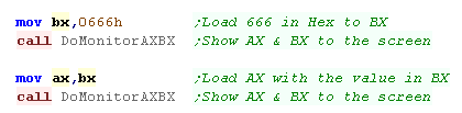
| We can do the same commands with BX,CX and DX.... they also have
H and L parts (BH,CL etc) Lets give 16 bit register BX a value (666h) ... then let's MOVe that value to AX |
 |
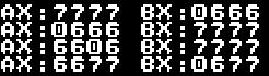
| The results can be seen here... |  |
| There may be times we want to swap the values in two registers
over... we could do two MOV commands, and store in a temporary
register like CX... but that would be wasteful... We have a special XCHG command.. this will swap two 16 bit registers over... or even two 8 bit parts over! Lets use it to do some swaps! |
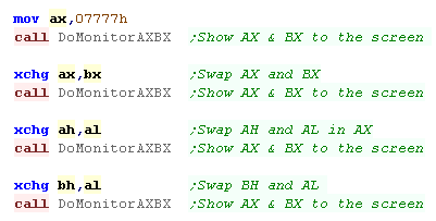 |
| We can see the results of the swaps... first we swapped AX and BX. Next we swapped AH and AL Finally we swapped BH and AL |
 |
| We've looked at the ADD and SUB commands for increasing and
decreasing values - but there is another way! Many times we'll want to change a register - increasing it, or decreasing it by 1 - we can use INC and DEC for this. |
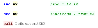 |
| Here's the result These commands use fewer bytes so are faster and smaller... they'll be handy for loop counters and things like that. |
 |
| Lesson 1is over!... What we've covered here may
seem confusing - and it may be a little disappointing! If you don't understand what you've seen, then try changing some of the values and writing your own commands, it should be more clear... If you don't see how this can help you write games... don't worry, you need to understand a lot of commands - but they'll soon build up and it will be more clear. |
 |
1. Immediate Addressing
(Load values from immediate numbers)
| This is the mode we used in the first lesson - we're just load
in fixed values specified in the ASM code... This works the way we saw before with AX,BX,CX and DX - and their 8 bit counterparts |
 |
| Here is the result |  |
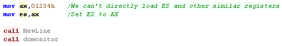
| As well as the 'main' registers - we have 'Segment registers' -
these have special purposes for addressing.... we'll learn more
about them soon! The Segment registers CS,DS ES and SS cannot be set via immediate methods - we'll have to load another register then transfer the value. |
|
| ES has changed as requested | 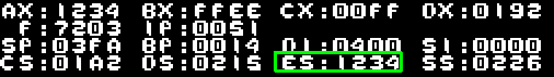 |
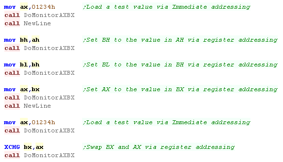
2. Register Addressing
(Value in a register)
| WE also looked at this before as well - 'Register Addressing' is where both source and destination parameters of a command are registers |
 |
| Here is the results | 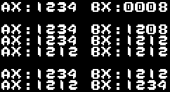 |
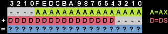
We can read from an address by specifying it with square brackets [addr] This is where our 'Segments' come into play (CS/DS/ES/SS registers) The 8086 uses a 20 bit address bus - but the registers are only 16 bit - how do we specify the remaining 4 bits? Well, these are taken from a 'Segment' register! The bottom 16 bits are taken from a register or fixed immediate value A segment register is added to the top 16 bits of the address For example if we use register AX, by default the DS segment register will be used... the resulting register will be: |
 |
| Lets set our data segment up to point to our code... we can set
the AX register to our code segment by specifying @Code Next lets read AX from offset 000Ch... (Don't worry about the PUSH and POP statements - we'll cover them soon) |
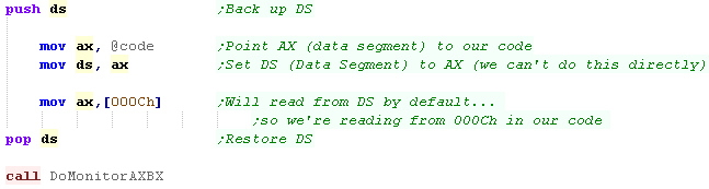 |
| We've loaded in a word from RAM... not the bytes are reversed - because the system is Little Endian | 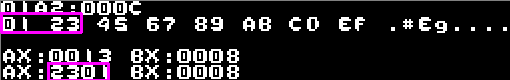 |
| Lets define some test data that we can read back later... | 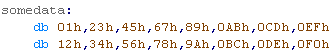 |
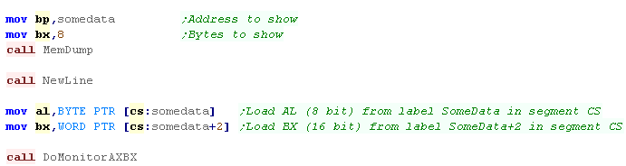
| We can load a register from an address label... for example the
'SomeData' label in our code segment. When we want to load from a label in this way, we need to specify this with an extra specifiet: BYTE PTR tells the assembler we want to load an 8 bit BYTE from the label WORD PTR tells the assembler we want to load an 16 bit WORD from the label If we put a code segment name and colon before an address - we will override the segment which otherwise defaults to DS... for example, lets load from the code segment CS |
 |
| We've loaded two words from our test data. | 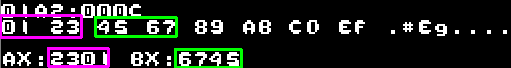 |
| We can save data to ram addresses in the same way. | 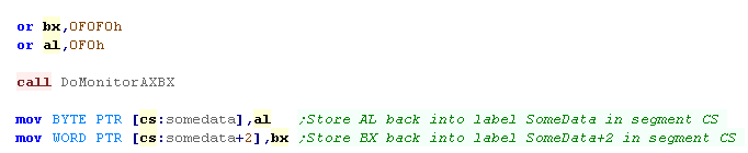 |
| The values are saved back to ram | 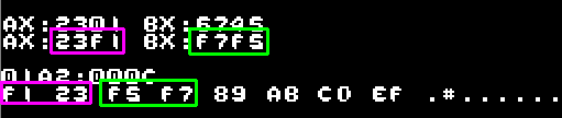 |
4. Register Indirect Addressing
(value in address contained in a register)
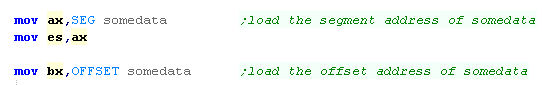
| Before we use this mode, we need to learn how to calculate the
Segments and offsets within those segments in our code.. We want to get the segment and address of the 'somedata' label. We can get the Segment with the SEG statement, and the offset with the OFFSET statement |
 |
| Now we have the registers set up... lets use Register Indirect
Addressing! |
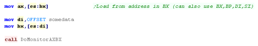 |
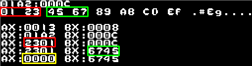
| Lets load some data from ES:BX (Data Segment ES - offset
BX) We can use special registers DI and SI (Destination Index and Source Index) in the same way. In the first examples we specified the Extra Segment - if we don't it will default to DS |
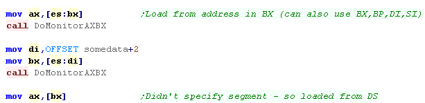 |
| we were able to load AX and BX from our test data... When we re-read in AX without specifying ES: it read in from the Data Segment DS - and read in 0000 |
 |
5. Based Addressing (AKA Indexed
Addressing) (value in Address contained in a register plus
immediate value)
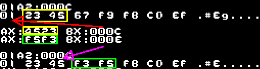
| We looked before at reading in from a label with a numberic
offset BUT we can do the same with a value in a register!... we can specify a register and a immediate numeric offset! We can read in from a register with offset... and write back in the same way... |
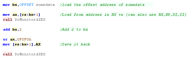 |
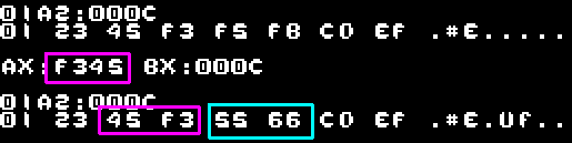
| BX was 000Ch - so when we read in we got address BX+1 - $000Dh We added 2 to bx making it $000Eh, so when we wrote back to BX+1 , we wrote to $000F |
 |
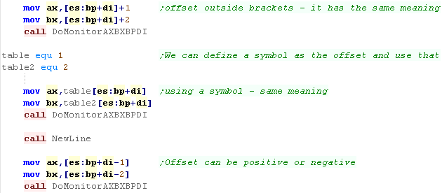
| We can define a symbol with an offset position, and use that
register as a pointer to a bank of settings. For example lets define 'SecondVariable' at position +2 , and a third called 'ThirdVariable' at position +4 We can now Read it's value with this or write it back. We could change the BX pointer to change the bank - for example to use a common player routine for 2 different players |
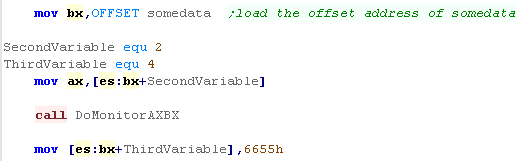 |
| We read in AX from BX+2 (as Secondvariable=2) we wrote back to BX+4 (as ThirdVariable=4) the value 6655h |
 |
|
We've used positive base
pointers here, but we can use negative ones too! Unlike the Z80, On the 8086 the displacement can be an 8 or 16 bit number! |
6. Base plus indexed Addressing
(Sum of two registers)
| We can use registers DI/SI as an offset with BX/BP - where the
two registers are added together... There's a limit to the registers we can use for this... we can use BX+DI, BX+SI, BP+DI, BP+SI |
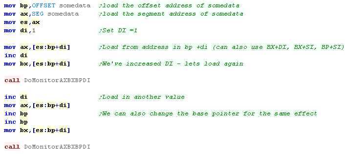 |
| We've read in from the addresses in the test data resulting from the BP+DI calculation | 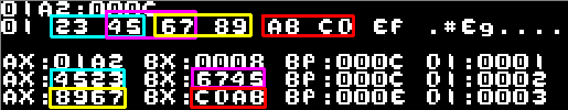 |
|
Beware...
these kind of commands only work with BX+DI, BX+SI, BP+DI,
BP+SI... Whats worse, the assembler won't warn you if you're being stupid and trying to use them - the code won't work... so be careful, or you'll waste hours trying to work out why your code isn't working! |
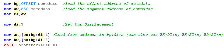
7. Base plus index with
displacement Addressing (Sum of base register, index
register, and displacement)
| Combining the previous two ideas, We can use a Base Register -
an index register, and an immediate displacement We can also use BX+DI+n, BX+SI+n, BP+DI+n, BP+SI+n |
 |
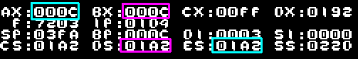
| The calculation will be applied, and the correct addresses loaded. | 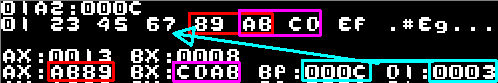 |
| Different assemblers and source code may use different
formats Depending on the syntax, you may see the displacement outside the brackets - the result is the same. We can also use symbols to make things clearer! |
 |
Setting Segment and Offset!
| We looked before at using the statement SEG to get the segment, and the offset with the OFFSET statement, but there is a shortcut! | |
| We have two special commands for loading 'Far pointers'... these
set a full 20 bit address from a label. Setting both the DS/ES segment register and AX/BX/etc with a single command. |
 |
| LDS has loaded in DS and BX, LES has loaded in ES and AX We can use AX,BX,CX,DX,SI,DI as the parameter, but only DS and ES as the segments - there's no LSS or LCS! |
 |
|
We've
covered a lot of different addressing modes here very
quickly... you may be confused which registers can be used in
which modes -and when you can use them... The best thing is to give it a go! Try changing the examples and see what works, and what doesn't! |
Going LOOPy
| Lets use LOOP to effect a repeat... This command uses CX as a loop counter... CX will be reduced, and a jump to the label specified will occur if CX is not zero... We'll use s Monitor function to show the value s of registers and flags. |
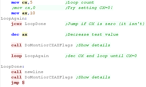 |
| The loop will run until CX=0 | 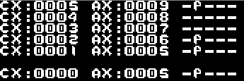 |
| What was that JCNZ for... well it will jump out of the loop if
CX=0... Without this if CX=0 when the loop starts, the first LOOP command would decrease CX to -1 (65535) ... this would cause the loop to occur 65 thousand times! |
|
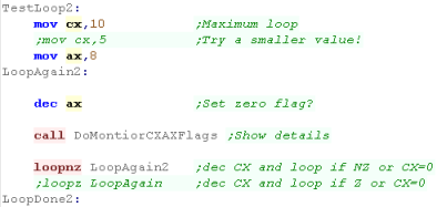
| There's are some alternative loop commands... LOOPNZ and
LOOPZ... Like LOOP these use CX as a loop counter and will repeat until CX=0, but there's another thing that can end the loop... LOOPZ will also end if the Zero flag is set LOOPNZ will also end if the Zero flag is not set It's important to understand that LOOP itself does not alter the Zero flag (Z) - so these commands allow the loop to end depending on the loop count CX reaching 0 OR the status of the Zero flag (Z)... |
 |
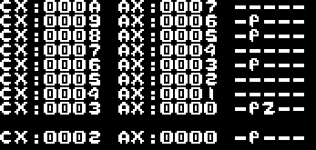
| The loop ended before CX reached Zero! Why? because when AX reached zero, the Z flag was set, and this caused the loop to end due to the loopNZ command. |
 |
Fun with Flags!
To understand conditional jumps we need to
have an understanding of The 8086 processor Flags... these are set during
various commands, and their meaning will vary in some cases...
For example... the Zero (Z) flag is set when a subtract operation results in zero - or where two values compared are equal...
Carry (C) is set when an ADD command overflows a register, or when a ROTate command pushes a 1 bit out of a register.
For example... the Zero (Z) flag is set when a subtract operation results in zero - or where two values compared are equal...
Carry (C) is set when an ADD command overflows a register, or when a ROTate command pushes a 1 bit out of a register.
Flags: ----ODIT
SZ-A-P-C
| Name | Meaning | Command to set Flag |
Command to clear Flag |
|
| T | Trap | 1=Cause INT2 every instruction |
||
| D | Direction | Used for 'string' cunctions |
STD | CLD |
| I | Interrupt enable | Allow maskable hardware interrupts |
STI | CLI |
| O | Overflow | 1=Overflow (sign changed) |
||
| S | Sign | 1=Negative 0=positive (top bit of reg) |
||
| Z | Zero | 1=Zero |
||
| A | Aux carry | Used as Carry in BCD |
||
| P | Parity | 1=Even no of 1 bits (8 bit) |
||
| C | Carry | 1=Carry/Borrow caused by last ADD/SUB/ROT instruction |
STC (see CMC) | CLC |
| Don't
worry about all the flags at this stage, - ones like Trap
Direction and Interrupt are not relevant to conditions You won't need them in this example, and depending on the commands you use, you may not need to! |
|
Conditions and Jumps
We have a variety of jump commands... and in
some cases, one command has two possible names as a convenience for the
programmer...
for example JA and JNBE are the same command
- they compile to the same bytecode , but the assembler understands two
possible command names to make it easier for us to remember the command
meanings!
| Command |
Details |
Flags |
| JA / JNBE short-label | (Unsigned) above/not below nor equal | (CF AND ZF)=O |
| JBE / JNA short-label | (Unsigned) below or equal/ not above | (CF OR ZF)=1 |
| JC / JB / JNAE short-label | (Unsigned) carry/below / not above nor equal | CF=1 |
| JCXZ short-label | Jump If CX Zero (see loop) | |
| JE / JZ short-label | equal/zero | ZF=1 |
| JG / JNLE short-label | (Signed) greater/ not less nor equal | ((SF XOR OF) OR ZF)=O |
| JGE / JNL short-label | (Signed) greater or equal/not less | (SF XOR OF)=O |
| JLE / JNG short-label | (Signed) less or equal/ not greater | ((SF XOR OF) OR ZF)=1 |
| JL / JNGE short-label | (Signed) less/not greater nor equal | (SF XOR OF)=1 |
| JMP target | Jump to label (byte or word target) | |
| JNC / JAE / JNB short-label | (Unsigned) above or equal/ not below | CF=O� AX>=cmp |
| JNE / JNZ short-label | not equal/ not zero | ZF=O |
| JNO short-label | not overflow | OF=O |
| JNP / JPO short-label | not parity / parity odd | PF=O |
| JNS short-label | not sign | SF=O |
| JO short-label | overflow | OF=1 |
| JP / JPE short-label | parity/ parity equal (bits 0-7 only) | PF=1 |
| JS short-label | sign | SF=1 |
The best way to test the flags and conditions
is to try them in practice.
Zero Flag (Equals)
| The Zero flag is set when the result of a command is zero... This can happen for two reasons... if a subtraction/DEC command results in zero, or if the two compared values are equal This is because CMP sets the flags the same as if a subtraction occurred, but only the flags are changed if a register overflows back to zero, Z will also be set - so adding 1 to 0FFFFh will also result in a Z flag |
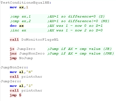 |
| A Z will be shown to the screen by the jump if the Z flag was set |  |
Greater and Less with Unsigned numbers
| The compare commands we use will be different depending on if
our numbers are signed (-32768 to 32767) or unsigned (0-65535) We have conditions for > < >= and <= |
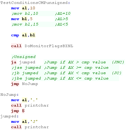 |
| You'll need to try different values to see the result |  |
Negative Numbers
Negative numbers in assembly are
confusing!... An 8 bit byte can only store values 0-255, so how can we do
negatives?
Well... if we add 1 to a byte containing 255 it will overflow back to zero... so adding 1 has the effect of subtracting 255...
Well... if we add 1 to a byte containing 255 it will overflow back to zero... so adding 1 has the effect of subtracting 255...
in the same way, adding 2 is the equivalent
of subtracting 254... and adding 255 is the equivalent of subtracting 1...
The formula for converting a positive number
to a negative one is:
XOR AX,0FFFFh ;Flip the bits
XOR AX,0FFFFh ;Flip the bits
INC AX
;Add one
| Negative number | -1 | -2 | -3 | -5 | -10 | -20 | -50 | -254 | -255 |
| Equivalent Byte value | 255 | 254 | 253 | 251 | 246 | 236 | 206 | 2 | 1 |
| Equivalent Hex Byte Value | FF | FE | FD | FB | F6 | EC | CE | 2 | 1 |
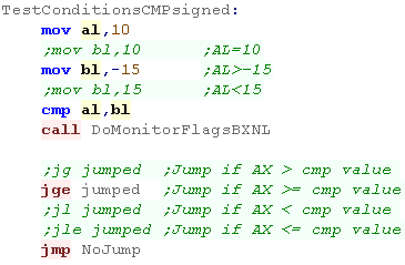
Greater and Less with Signed
numbers
| Because whether a registers value is positive or negative is
undefined in the register itself, we have to use different
commands when working with signed numbers than unsigned ones... We can specify -15 in our ASM code - the assembler will work out the equivalent byte value. |
 |
 |
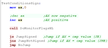
Sign bit testing
| We can also test the sign bit - if the top bit of the last
mathematical operation is 0 then the value is positive - if it's 1
then the value is negative. the S bit will be set if the result is <0 |
 |
 |
Parity bit testing
| The Parity bit is a bit odd... The 1 bits are summed in the first byte... if there's an odd number P=0 (odd)... if there's an even number P=1 (even) | 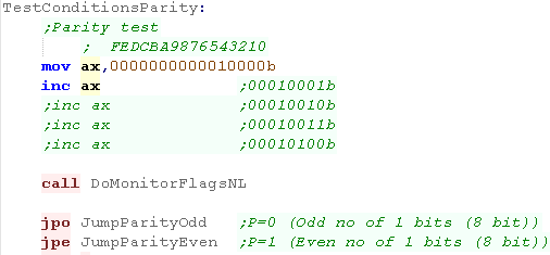 |
 |
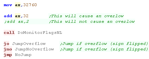
Overflow test
| The 'Overflow' flag is used
to check if a signed register has become invalid... an Unsigned register can store +32768 just fine - but in a signed register, this will effectively be -32768 This will cause a problem! so we have an overflow flag to check if this has happened. |
 |
 |
| We've looked at a
large variety of commands here - but you REALLY need to try them
yourself before they'll make sense. The example code above had many alternate test REMmed out - try unremming them! |
|
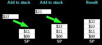
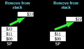
Stack Attack!
| 'Stacks' in assembly are like an
'In tray' for temporary storage... Imagine we have an In-Tray... we can put items in it, but only ever take the top item off... we can store lots of paper - but have to take it off in the same order we put it on!... this is what a stack does! If we want to temporarily store a register - we can put it's value on the top of the stack... but we have to take them off in the same order... The stack will appear in memory, and the stack pointer goes DOWN with each push on the stack... so if it starts at $2000 and we push 2 bytes, it will point to $1FFE on the 8086 we push bytes into the stack in pairs |
  |
|
Today
example has a lot of 'tricks' we wont cover today that allow
the stack to be shown to the screen - normally a call would
use the stack But we're using a fake stack so that only the push pop commands affect the shown stack - this is to allow the shown stack to only show the effect of the example commands - not the stack and register dump routines |
Pushing Registers
onto the stack and popping them back
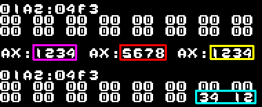
| Lets look at an example of the stack! We'll load AX with 1234h - and push it onto the stack We'll then load AX with 5678h Finally we'll pop AX off the stack - we'll show the state of AX at each stage. |
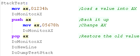 |
| We loaded 1234h into AX we then pushed it Onto the stack - it's reversed because the 8086 is little endian We then load AX with 5678h Finally we popped AX of the stack - getting back the value 1234h |
 |
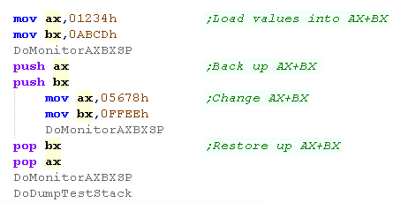
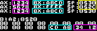
| We can push multiple items onto the stack, and restore them back
in the same way. The important thing is we take them off in the opposite order to how we pushed them onto the stack In this case we push AX then BX - and pop off BX then AX |
 |
| We can see each item pushed on the stack was restored
successfully... Note we pushed AX (1234h) onto the stack first, then BX (ABCDh) - but BX comes before AX on the stack... this is because the stack pointer goes DOWN after each push |
 |
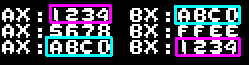
| We can reverse the order we pop them off the stack... In this case we reversed the pop order of BX and AX |
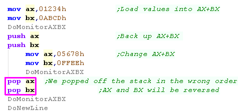 |
| AX and BX were reversed after the POPs You don't want to do this by accident - but there will be times you will want to do it on purpose! |
 |
Nested Stack
pushes
| Because of the way the
stack works, we're effectively nesting the pushes onto the
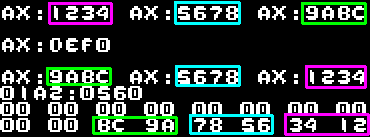
stack... lets make a clear example to really show this... First we'll push 1234h, then 5678h then 9ABCh we'll then pop them all off the stack |
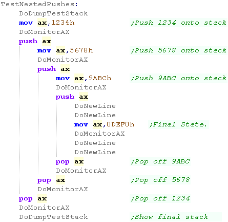 |
| The three values are pushed onto the stack and popped back
intact... Again, because the stack moves backwards, the values on the stack are reversed |
 |
Pushing Flags and
transferring flags to the accumulator!
| We can push all the registers in this way, but we will sometimes
need to push the flags... We need a special commands PUSHF and POPF for this purpose - they work in the exact same way as any other register. If we want control over the main flags, we can transfer them to AH with SAHF , or transfer the flags to AH with LAHF This only allows us access to the main flags: SZ-A-P-C The flags are 16 bit, and both bytes are pushed onto the stack - in fact, this is a good way to set flags like the Trap flag (Flags:----ODIT), which cannot be directly set... we can push onto the stack, and pop back into AX and vice versa In the example we push all the flags with PUSHF and pop them back into AX |
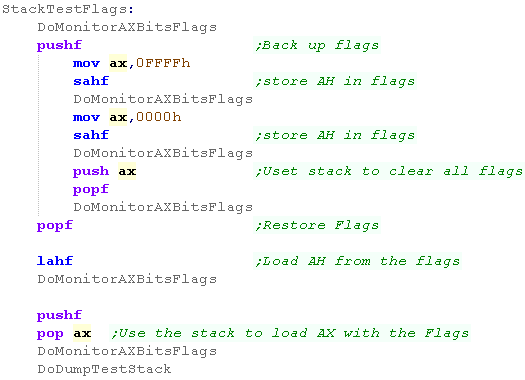 |
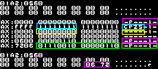
| We were able to Push and Pop the flags
onto the stack.. We used SAHF to store AH to the flags... setting them all to one - and also to zero We were also able to push the flags onto the stack and transfer them all into AX |
 |
Calls and the stack
| It's not just our code that uses the stack... in fact CALL
statements use the stack too... every time we run a call, we're
effectively pushing the RETurn address onto the stack... When we use a RET statement, we're effectively popping the program counter (IP) off the stack... Lets try it!... We're going to call a subroutine... That subroutine will push BX onto the stack, It will then run another subroutine twice, before restoring BX Finally it will return... lets see the results! |
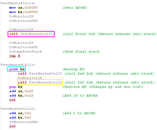 |
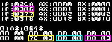
| Due to the way the test code works, the return addresses aren't
quite the same on the stack as the Monitor dumps The return address of the first TestNestedCall1 is pushed onto the stack, Next BX will be pushed onto the stack... TestNestedCall2 will be executed, it's return address will be pushed... the second call of TestNestedCall2 will cause it's return address to overwrite the first (as it's been popped off in the previous RETurn) the end result? BX is unaffected by TestNestedCall2 due to the POP of BX in TestNestedCall1 |
 |
|
You
have to be careful to remove everything your subroutine put on
the stack before the return... otherwise the RET command will
mistake one of your pushed values for the return address and
run something crazy! DON'T SAY I DIDN'T WARN YOU!... but if you're super clever you can take advantage of things like this to do clever stuff! |
Using the stack for
parameters
| The RET command on the 8086 has a special trick... after the
return it can pop a number of bytes of the stack... The reason for this is it's common to push parameters onto the stack before calling a function - the function will use those parameters, and this is a way of removing them. In this example we'll push 4 bytes (2 words) onto the stack, and the function will load them to CX and DX, then return... The RET statement will remove the 4 bytes |
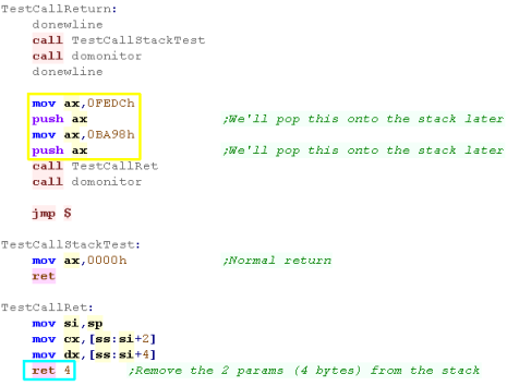 |
| CX and DX will receive the values pushed on to the stack | 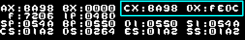 |
Macros
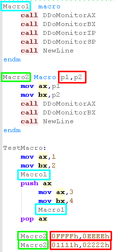
| The monitor tools for this example used a lot of Macros - we're
not going to cover those here... but lets look at a simple macro Macros contain multiple commands... then we can use the macro name in our code like a command! A macro is different to a call... the Assembler REPLACES any reference to the macro with its contents. This makes the code faster as there's no call, but bigger, as there will be duplication of the call contents. macros allows us to do things a call cannot (in my tutorial code I swapped out the stack pointer so the call to the monitor would not affect the test stack) Macro's can use parameters - these will be swapped out by the assembler - they're great for defining blocks of code we may want to use many times |
 |
| Here's the result. | 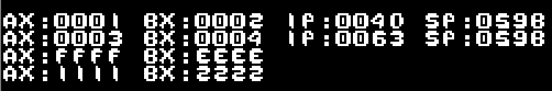 |
AND, OR and XOR!
There will be many times when we need to change some of the bits in a register, we have a range of commands to do this!
AND will return a bit as 1 where the bits of both the destination and parameter are 1
OR will set a bit to 1 where the bit of either the destination or the parameter is 1
XOR means Exclusive OR... it will invert the bits of the destination with the parameter - it's called EOR on some systems
NOT also inverts the bits... however it takes no second parameter, it's the same as XOR with the parameter 255/65534
Effectively, when a bit is 1 - AND will keep it... OR will set it, and XOR will invert it
A summary of each command can be seen below:
| Command | Destination register | Parameter | Result |
| AND | 1 0 1 0 |
1 1 0 0 |
1 0 0 0 |
| OR | 1 0 1 0 |
1 1 0 0 |
1 1 1 0 |
| XOR | 1 0 1 0 |
1 1 0 0 |
0 1 1 0 |
| NOT | 1 0 |
0 1 |
| Command | mov al,0b10101010 xor al,0b11110000 |
mov al,0b10101010 and al,0b11110000 |
mov al,0b10101010 or al,0b11110000 |
| Result | 0b01011010 | 0b10100000 | 0b11111010 |
| Meaning | Invert the bits where the mask bits are 1 |
return 1 where both bits are1 | Return 1 when either bit is 1 |
In the Z80 tutorials, we saw a visual representation of how these commands changed the bits - it may help you understand each command.
| Sample | XOR al,0b11110000 Invert Bits that are 1 |
AND
al,0b11110000 Keep Bits that are 1 |
OR al,0b11110000 Set Bits that are 1 |
 |
 |
 |
 |
We also have a 'NEG' command - it flips the
bits and adds one, converting a positive number into a negative, or
vice-versa
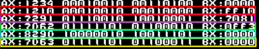
| We'll try each of the commands on AX with some test values, showing the results at each stage | 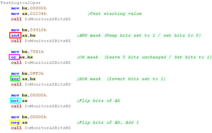 |
| Our starting value is 1234 AND removed the bits that were zero in it's parameter (FF10), changing 1234 into 1210 OR set some of the bits (those that were 1 in it's parameter (7081), changing 1210 into 7291 XOR flips the bits that were 1 in it's parameter (0FF3) changing 7291 into 7D62 NOT flips all the bits, changing 7D62 into 829D NEG flips all the bits and adds one, changing 829D into 7D63 (it was 7D62 before the NOT) |
 |
|
AND
doesn't just alter the register - it also sets the flags
accordingly - so the Z flag will be set if the result is
zero... If you want to set the flags in this way, but leave the register unchanged use TEST - it has the same effect on the flags as AND, but leaves the registers unchaged! |
Bit shifting
| There will be many times in assembly when we may want to shift
bits around within registers... We may wish to process a byte one bit at a time, move a top nibble to a low nibble, and generally shift data around for the format we need. bit shifting also allows simple multiplication, shifting to the left effectively doubles a value, shifting to the right effectively halves it. We have a wide variety of bit shifting commands... on the 8086 we can only shift 1 bit at a time, on the 80186+ we can shift multiple bits! ROR (ROtate Right) shifts the bits around a register to the right - no data is lost, any bits that leave the right hand side come back on the left. RCR (Rotate through Carry Right) is similar, but the 'Carry' flag acts as an extra bit... when a bit is pushed off the right it goes into the carry, and the previous carry value becomes the leftmost bit... This is handy for processing data one bit at a time. SHR (SHift logical Right) - this shifts bits to the right, new top bits are zero - any bits pushed off the right are lost. SAR (Shift Arithmatic Right) - this also shifts bits to the right, again any bits pushed off the right are lost, but the top bit is the same as the last top bit - this means it can be used with negative numbers, and the sign won't change, we can use it to halve negative values! |
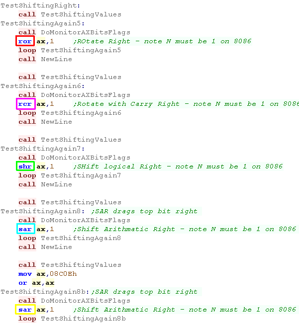 |
| The result of each command can be seen here | 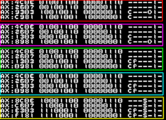 |
| Each commands has an equivalent Left shifting function ROL (ROtate Left) RCL (Rotate Carry Left) SHL (SHift logical Left) SAL (Shift Arithmatic Left) - with negative example |
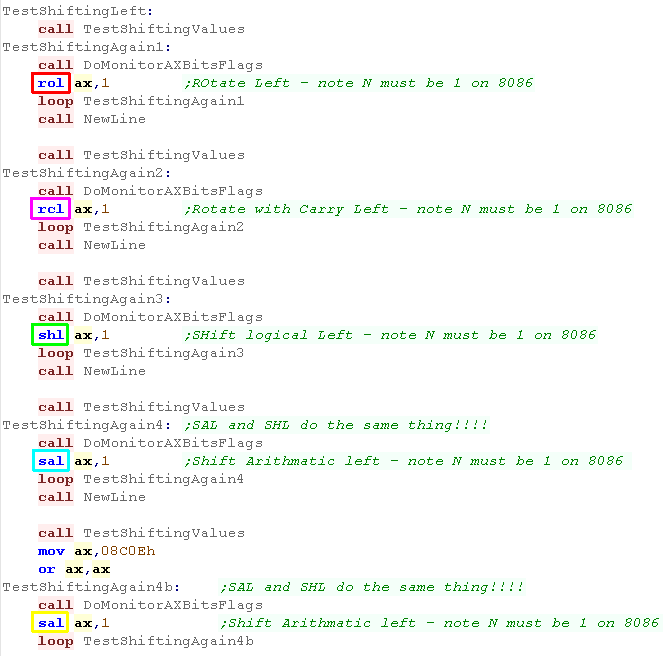 |
| The results of each command can be seen here. | 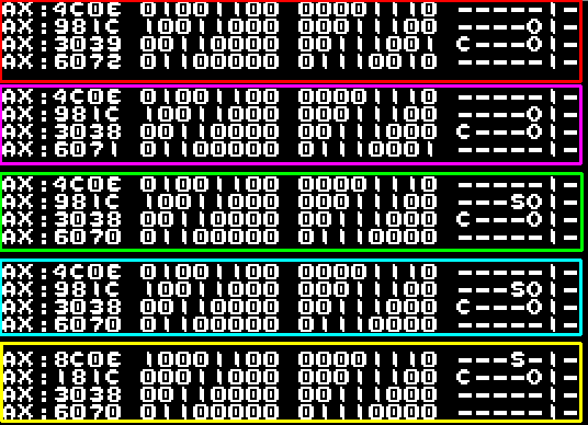 |
|
While SAR and SHR are
different... SHL and SAL do the same thing! it doesn't matter
which you use - so don't worry! |
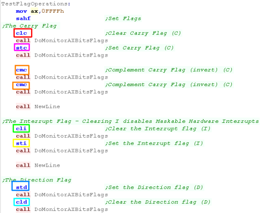
Setting and Clearing flags
We looked at various tricks with flags in previous lessons, but
we didn't cover the range of commands to set and clear flags
arbitrarily... we have several options:
|
 |
||||||||||||||||
| Here are the results! | 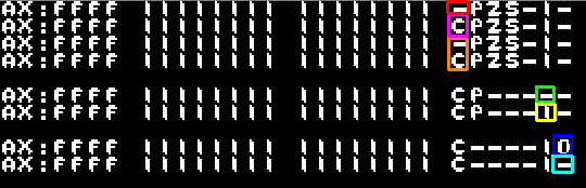
|
| Wondering
how you're supposed to deal with the other flags? well there's
no commands to directly set or clear them! You'll have to do something else - the best thing to do is push the flags onto the stack, alter them on the stack (or pop them into ax) and then pop them back SAFH probably won't help, as that only affects the bottom half of the flags register |
|
ADC, SBB - using the Carry (borrow) for
32 bit!
| Although our registers are only 16 bit, we can use a pair of
them together to make a 32 bit pair... one register will be the
Low part of the 32 bit pair, the other will be the High part When we do addition or subtraction, the Carry flag can be used as a Carry or Borrow to add or remove from the High register... (the Carry flag functions as a borrow for subtraction) We first do addition or subtraction from the Low Register (BX in this example) using the regular ADD or SUB... then we perform the addition or subtraction with the carry on the high part using ADC (add with Carry) or SBB (Subtract with Borrow) If we don't want to add or subtract anything from the H you would do ADC ax,0 or SBB ax,0 - because you'd still need to apply any carry or borrow to the high register |
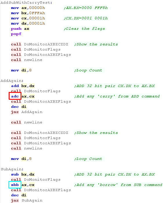 |
| when the Carry flag is set.. the ADC or SBC adds or subtracts an extra 1 from the top register | 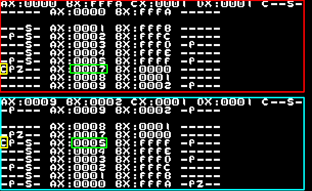 |
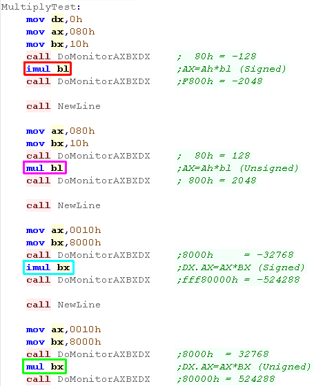
Multiplication
| Unlike many 8 bit processors, the 8086 has multiplication
commands... they can work with bytes or words, but the result is
always twice the size... there are two command, IMUL works with
signed numbers, MUL works with unsigned numbers... if you use an 8 bit parameter (eg BL) then the command: IMUL BL will perform AH*BL - returning the result in AX ( MUL BL would be the same) if you use an 16 bit parameter (eg BX) then the command: IMUL BX will perform AX*BX - returning the result in DX.AX - a 32 bit pair where DX is the High word, and AX is the low word (MUL BX would be the same) |
 |
| The results of each command are shown here. | 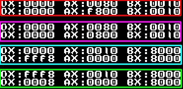 |
Division
| When performing Division there are a couple of 'gochas' we have
to be ready for! The first is the classic 'Division by zero' (if it takes 1 person 10 minutes to eat a cake, and 2 people 5 minutes - how long will the cake last if 0 people eat it?)... Division by zero causes Interrupt 0 and will lock the machine. The other is 'Overflow)... if we Divide 1000 by 1, and the result is to be stored in a byte, it won't fit! this is called overflow and causes Interrupt 4 We should range check our parameters first! Just like before IDIV works with signed parameters, and DIV works with unsigned ones IDIV BL will perform AX / BL - returning the integer result in AL and the remainder in AH (DIV BL would be the same) if you use an 16 bit parameter (eg BX) then the command: IDIV BX will perform DX.AX / BX (where DX.AX is a 32 bit pair) - returning the integer result in AX and the remainder in DX (DIV BX would be the same) |
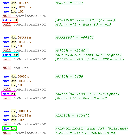 |
| The results of each command are shown here. | 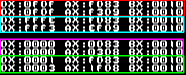 |
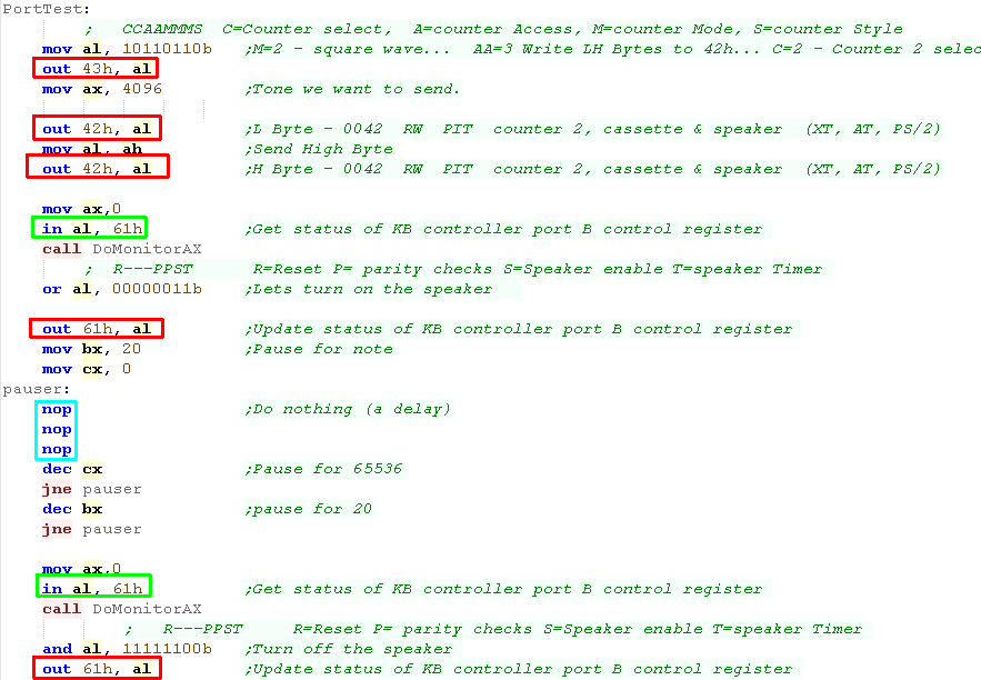
Ports, and NOP
| 'PORTS' are the connections from the main CPU to peripherals -
this is how we transfer data to and from these devices. This example sends data OUT to port 42h (the speaker)... and reads it IN from port 61h (so we can enable the speaker bits,but leave the others alone) We'll look more at the speaker example in a later lesson... Another command we show here is NOP... this command does literally nothing, here we use it as a very crude delay... but it can also be used in self modifying code (code that alters it's own code) |
 |
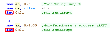
Interrupts
| Interrupts are tasks which override our program and run
immediately... Hardware interrupts are where a device is taking control.. software interrupts occur for different circumstances (Like Division by zero), and we can even cause them ourselves with an INT command... (like a RST on Z80 / SWI on ARM or TRAP on 68000) INTerrupts are used by DOS - and we can use them as OS calls to start DOS functions such as printing a string and returning to the OS |
 |
| Software interrupts call addresses from 0000:0000+... each uses
2 words - the first is the code segment of the interrupt handler,
the second is the address of the handler... We can program a custom interrupt handler for INT4 (We need to use RETI to end the interrupt handler Another interesting one is INT2 the 'Debugging Step Trap' - if we turn on the Trap flag this interrupt will occur every command - it's intended for trace debugging. |
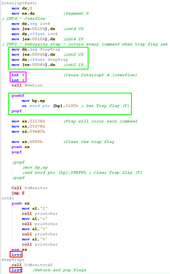 |
| Our INT4 ran twice... and the Step trap shows the changes of AX while the Trap flag was on | 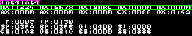 |
| What ports and
interrupt numbers do is a mystery - it all depends on the
machine setup - you'll need to check the documentation of the
machine to understand using the OS Interrupt numbers, and what
the ports do with the attached hardware. |
|
String commands perform a sequence of actions
on a range - the function varies by command... for example MOVSW will copy
a word from address (DS:SI) to (ES:DI)... but it will only do one!
If we want to do a sequence, we use the REP
command ... eg "REP MOVSW"
Rep only works with String commands - it
repeats the command CX times
This also uses the Direction flag - if the
Direction flag is set, the operation goes backwards im memory (towards
zero)
| Command |
Source |
Destination |
Notes |
|
| CMPSb/w |
DS:SI | ES:DI | Compare bytes between source and destination (Use REPZ / REPNZ) | |
| LODSb/w |
DS:SI | Load a byte from the source | ||
| MOVSb/w |
DS:SI | ES:DI | Move Data from Source to Destination in Words or Bytes | |
| SCASb/w |
|
Scan Destination for AX (Use REPZ / REPNZ) | ||
| STOSb/w |
AX | ES:DI | Set bytes to AX/AL |
|
String
functions are like the LDI command on the Z80 - they do a job
then stop, so we can do some extra processing Adding REP is like LDIR - and processes the string repeatedly until CX reaches zero |
MOVS - MOVe to String/ STOS - STOre
String
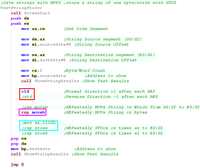
| MOVSB/W will move a sequence of bytes
or words from DS:SI to ES:DI... we can use REP to repeat - this will copy CX bytes or CX words. we can use STD to reverse the direction of the copy If we want to store a sequence of the same byte or word, we can use STOSB/W instead. |
|
| We copied 3 bytes from the source to the destination in the first example | 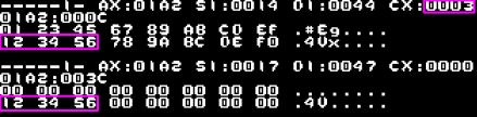 |
| in the second screenshot I enabled STD, reversing the procedure,, and used REP STOSW to copy AX to a range of 3 words | 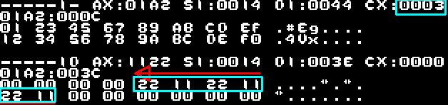 |
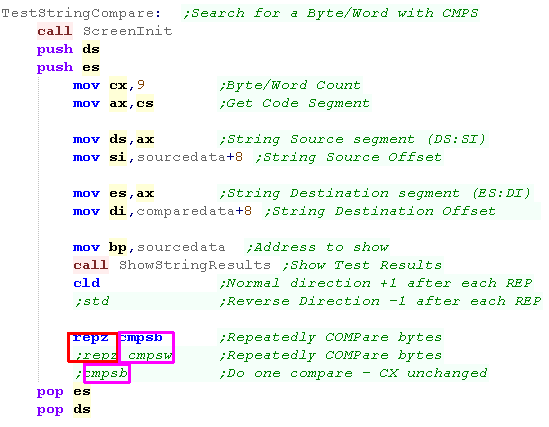
CMPS - CoMPare String
| CMPSB/W compares two sequences, one at
DS:SI and one at ES:DI We needs to use REPZ or REPNZ to repeat it - and set CX. REPZ will continue until the strings no longer match REPNZ will continue until the strings start to match. |
|
| The routine scanned the string until
they stopped matching (and the Zero flag stopped being set)... DI points to the following byte after the routine ends... also note CX did not reach zero |
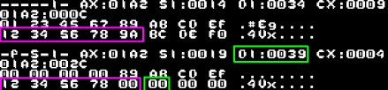 |
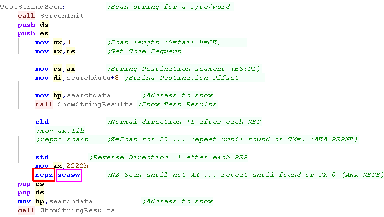
SCAS - SCAn for String
| SCAS will scan a string and compare it
to AX (or AL) We can use REPZ to scan until the bytes don't match AX/AL or REPNZ to scan until the bytes do match AX/AL |
 |
| We set the Direction flag with STD so we went backwards... scanning words until we found one that didn't match AX - DI then points to the word before | 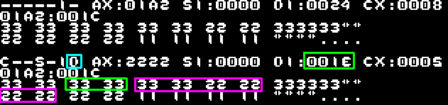 |
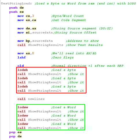
LODS - LOaD from a String
| If we're looking to process bytes or words from a sequence we
can use LODS... like the z80 ldi command, this can be used as a
quick way of reading in from a range and performing commands on
those read in bytes or words. In this example we'll read in bytes with LODSB, then words with LODSW from the string. this command can be used with REP, but I'm not sure what the purpose would be - as SCAS can be used for scanning, and the repeat will not do anything with the read in data. |
 |
| We loaded in 3 Bytes and then 3 words | 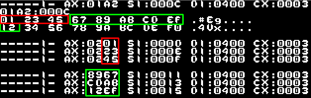 |
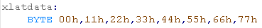
XLAT - Translate
| XLAT is a translation command - it uses a lookup table in
[DS:BX] and loads AL with the value at offset AL (AL = [DS:BX+AL]) In this example we use XLAT to convert a number to a pair of nibbles with that number... Not particularly useful, but it will show what the command does. |
 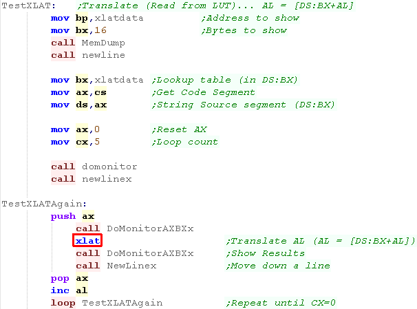 |
| the XLAT command has converted AL according to the look up table | 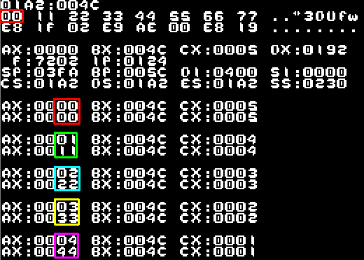 |
|
Phew!
we've covered all the major 8086 commands! We should be able to make a decent effort at some programming now... Join in on the platform specific series next, In which we'll learn about the DOS and WonderSwan hardware! |
Appendix
| Mnemonic | Description | Example | Valid Regs | Flags affected |
| AAA | ASCII Adjust for Addition. Treats AL as an unpacked binary coded decimal number | AAA | o s z A p C | |
| AAD | ASCII Adjust for Division. AL=AL+(AH*10), AH=0. | AAD | o S Z a P c | |
| AAM | ASCII Adjust for Multiplication. We can use the normal MUL command then use AAM | AAM | o S Z a P c | |
| AAS | ASCII Adjust for Subtraction. This treats AL as an unpacked binary coded decimal number | AAS | o s z A p C | |
| ADC dest,src | Add src and the carry flag to dest. | ADC CX,1000h | O S Z A P C | |
| ADD dest,src | Add src to dest. | ADD CX,1000h | O S Z A P C | |
| AND dest,src | Logical AND of bits in dest with Accumulator scr. | AND AX,1100h | O S Z A P C | |
| CALL dest | Call Subroutine at address dest. | CALL 1000h | - - - - - - | |
| CBW | Convert the 8 bit byte in AL into a 16 bit word in AX. | CBW | - - - - - - | |
| CLC | Clear the Carry Flag. C flag will be set to Zero. | CLC | - - - - - C | |
| CLD | Clear the Direction Flag. D flag will be set to Zero. This is used for 'String functions'. | CLD | D - - - - - - | |
| CLI | Clear the Interrupt enable flag. I flag will be set to 0. This disables maskable interrupts. | CLI | I - - - - - - | |
| CMC | Complement the Carry flag. If C=1 it will now be 0. If it was 0 it will now be 1. | CMC | - - - - - C | |
| CMP dest,src | Compare the Byte or Word dest to src. This sets the flags the same as "SUB dest,src" would. | CMP AL,32 | O S Z A P C | |
| CMPSB CMPSW |
Compare DS:SI to ES:DI. This command can work in bytes or words. Sets flags like CMP | REPZ CMPSB | O S Z A P C | |
| CWD | Convert the 16 bit word in AX into a 32 bit doubleword in DX.AX. This 'Sign Extends' AX | CWD | - - - - - - | |
| DAA | Decimal Adjust for Addition. This treats AL as a packed binary coded decimal number. | DAA | O S Z A P C | |
| DAS | Decimal Adjust for Subtraction. This treats AL as a packed binary coded decimal number. | DAS | O S Z A P C | |
| DEC Dest | Divide Unsigned number AX or DX.AX by src. | DEC AL | O S Z A P - | |
| DIV src | Divide Unsigned number AX or DX.AX by src. AL=AX/src (8 bit) or AX=DX.AX/src (16 bit) | DIV CX | o s z a p c | |
| ESC #,src | This command is for working with multiple processors - it's not something you will need. | ESC 1,AH | - - - - - - | |
| HLT | Stop the CPU until an interrupt occurs | HLT | - - - - - - | |
| IDIV src | Divide Signed number AX or DX.AX by src. AL=AX / src (8 bit) or AX=DX.AX / src (16 bit) | IDIV CX | o s z a p c | |
| IMUL src | Multiply Signed number AX or DX.AX by src. AX=AL*src (8 bit) or DX.AX=AX*src (16 bit) | IMUL CX | O s z a p C | |
| IN dest,port | Read in an 8 bit byte or 16 bit word into dest (either AX or AL). Use DX for 16 bit port | IN AX,F0h | - - - - - - | |
| INC Dest | Increase Dest by one. This is faster than using ADD with a value of 1. | INC AL | O S Z A P - | |
| INT # | Causes software interrupt #. The flags are pushed onto the stack before call | INT 33h | - - - - - - | |
| INTO | INTO will cause Interrupt 4 if the Overflow flag (O) is set, otherwise it will have no effect. | INTO | - - - - - - | |
| IRET | Restore the flags from the stack and return from an Interrupt. | IRET | O S Z A P C | |
| Jcc addr | Jump to 8 bit offset addr if condition cc is true. | JO ErrorHandle | - - - - - - | |
| JCXZ addr | Jump to 8 bit offset addr if CX=0. | JCXZ NoLoop | - - - - - - | |
| JMP addr | Jump to address addr. | JMP BX | - - - - - - | |
| LAHF | Load AH from the Flags. This only transfers the main flags: SZ-A-P-C | LAHF | - - - - - - | |
| LDS reg,addr | Load a full 32 bit pointer into DS segment register and register reg. | LDS BX,TestPointer | AX, BX, CX, DX, SI, DI | - - - - - - |
| LEA reg,src | Load the effective address src into reg. | LEA CX,[BX+DI] | AX, BX, CX, DX,SI, DI, BP, SP | - - - - - - |
| LES reg,addr | Load a full 32 bit pointer into ES segment register and register reg. | LES AX,MyLabel | AX,BX,CX,DX,SI,DI | - - - - - - |
| LOCK | Enable the LOCK signal. This is for multiprocessor systems. | LOCK | - - - - - - | |
| LODSBLODSW | Load from DS:SI into AX or AL. This command can work in bytes or words. | LODSB | - - - - - - | |
| LOOP addr | Decrease CX and jump to label addr if CX is not zero. | LOOP LoopLabel | - - - - - - | |
| LOOPNZ addr LOOPNE addr |
Decrease CX and jump to label addr if CX is not zero and the Zero flag is not set. | LOOPNZ LoopLabel | - - - - - - | |
| LOOPZ addr LOOPE addr |
Decrease CX and jump to label addr if CX is not zero and the Zero flag is set. | LOOPZ LoopLabel | - - - - - - | |
| MOV dest,src | Move a value from source src to destination dest | MOV AX,BX | - - - - - - | |
| MOVSB MOVSW |
Move a byte or word from DS:SI to
ES:DI. (Like Z80 LDIR) This command can be combined with repeat command REP, to repeat CX times. |
REPZ MOVSB | - - - - - - | |
| MUL src | Multiply unsigned number AX or DX.AX by src.AX=AL*src (8 bit) or DX.AX=AX*src (16 bit) | MUL CX | O s z a p C | |
| NEG dest | Negate dest (Twos Complement of the number). | NEG AL | - - - - - - | |
| NOP | No Operation. This command has no effect on any registers or memory. | NOP | - - - - - - | |
| NOT dest | Invert/Flip all the bits of dest. | NOT dest | - - - - - - | |
| OR dest,src | Logically ORs the src and dest parameter together. | OR AX,BX | O S Z a P C | |
| OUT port,src | Send an 8 bit byte or 16 bit word from src (either AX or AL) to hardware port number port. Use DX for 16 bit port | OUT 100,AL | - - - - - - | |
| POP reg | Pop a pair of bytes off the stack into 16 bit register reg. | POP ES | AX, BX, CX, DX, SI, DI, SP, BP, CS, DS, ES, SS | - - - - - - |
| POPF | Pop a pair of bytes off the stack into the 16 bit Flags register. | POPF | O D I T S Z A P C | |
| PUSH reg | Push a pair of bytes from 16 bit register reg onto the top of the stack. | PUSH AX | - - - - - - | |
| PUSHF | Push a pair of bytes off the stack into the 16 bit Flags register. | PUSHF | - - - - - - | |
| RCL dest,count | Rotate bits in Destination dest to the Left by count bits, with the carry flag acting as an extra bit. | RCL AX,1 | O - - - - C | |
| RCR dest,count | Rotate bits in Destination dest to the Right by count bits, with the carry flag acting as an extra bit | RCR AX,1 | O - - - - C | |
| REP stringop | Repeat string operation stringop while CX>0. Decrease CX after each iteration | REP LODSW | - - - - - - | |
| REPE stringop REPZ stringop |
Repeat string operation stringop while the Z flag is set and CX>0. Decrease CX each time | REPZ CMPSB | - - - - - - | |
| REPNE stringop REPNZ stringop |
Repeat string operation stringop while the Z flag is not set and CX>0. Decrease CX each time | REPNZ CMPSB | - - - - - - | |
| RET | Return from a subroutine. | RET | - - - - - - | |
| ROL dest,count | Rotate bits in Destination dest to the Left by count bits | ROL AX,1 | O - - - - C | |
| ROR dest,count | Rotate bits in Destination dest to the Right by count bits | ROR AL,1 | O - - - - C | |
| SAHF | Store AH to the Flags. This only transfers the main flags: SZ-A-P-C . | SAHF | - S Z A P C | |
| SAL dest,count | Shift the bits for Arithmetic in Destination dest to the Left by count bits. | SAL AX,1 | O - - - - C | |
| SAR dest,count | Shift the bits for Arithmetic in Destination dest to the Right by count bits. | SAR AX,1 | O - - - - C | |
| SBB dest,src | Subtract src and the Borrow (carry flag) from dest. | SBB AL,BL | O S Z A P C | |
| SCASB SCASW |
Scan ES:DI and compare to AX or AL. This command can work in bytes or words. (Like CMP) | REPZ SCASB | O S Z A P C | |
| SHL dest,count | Shift the bits logically Left in destination dest by count bits. | SHL AX,1 | O - - - - C | |
| SHR dest,count | Shift the bits logically Right in destination dest by count bits. | SHR AX,1 | O - - - - C | |
| STC | Set the Carry Flag. C flag will be set to 1. | STC | - - - - - C | |
| STD | Set the Direction Flag. D flag will be set to 1. This is used for 'String functions'. | STD | D - - - - - - | |
| STI | Set the Interrupt enable flag. I flag will be set to 1. This enables maskable interrupts. | STI | I - - - - - - | |
| STOSB STOSW |
Store AX or AL to ES:DI. This command can work in bytes or words. | REP STOSB | - - - - - - | |
| SUB dest,src | Subtract src from dest. | SUB AX,BX | O S Z A P C | |
| TEST dest,src | Test dest, setting the flags in the same way a logical "AND src" would. Dest unchanged | TEST BX,64h | O S Z A P C | |
| WAIT | Wait until the busy pin of the CPU is inactive. | WAIT | O S Z A P C | |
| XCHG reg1,reg2 | Exchange the contents of registers reg1 and reg2. | XCHG BH,AL | - - - - - | |
| XLAT | Translate AL using lookup table DS:BX. AL is read from memory address [DS:BX+AL]. | XLAT | - - - - - - | |
| XOR dest,src | Logical XOR (eXclusive OR) of bits in dest with src. | XOR AX,BX | O S Z a P C |
| View Options |
| Default Dark |
| Simple (Hide this menu) |
| Print Mode (white background) |
| Top Menu |
| ***Main Menu*** |
| Youtube channel |
| Patreon |
| Introduction to Assembly (Basics for absolute beginners) |
| Amazon Affiliate Link |
| AkuSprite Editor |
| ChibiTracker |
| Dec/Bin/Hex/Oct/Ascii Table |
| Alt Tech |
| Archive.org |
| Bitchute |
| Odysee |
| Rumble |
| DailyMotion |
| Please note: I wlll upload more content to these alt platforms based on the views they bring in |
| 68000 Content |
| ***68000 Tutorial List*** |
Learn 68000 Assembly  |
| Hello World Series |
| Platform Specific Series |
| Simple Samples |
| Grime 68000 |
| 68000 Downloads |
| 68000 Cheatsheet |
| Sources.7z |
| DevTools kit |
| 68000 Platforms |
| Amiga 500 |
| Atari ST |
| Neo Geo |
| Sega Genesis / Mega Drive |
| Sinclair QL |
| X68000 (Sharp x68k) |
| 8086 Content |
| Learn 8086 Assembly |
| Platform Specific Series |
| Hello World Series |
| Simple Samples |
| 8086 Downloads |
| 8086 Cheatsheet |
| Sources.7z |
| DevTools kit |
| 8086 Platforms |
| Wonderswan |
| MsDos |
| ARM Content |
| Learn ARM Assembly |
| Learn ARM Thumb Assembly |
| Platform Specific Series |
| Hello World |
| Simple Samples |
| ARM Downloads |
| ARM Cheatsheet |
| Sources.7z |
| DevTools kit |
| ARM Platforms |
| Gameboy Advance |
| Nintendo DS |
| Risc Os |
| Risc-V Content |
| Learn Risc-V Assembly |
| Risc-V Downloads |
| Risc-V Cheatsheet |
| Sources.7z |
| DevTools kit |
| MIPS Content |
| Learn Risc-V Assembly |
| Platform Specific Series |
| Hello World |
| Simple Samples |
| MIPS Downloads |
| MIPS Cheatsheet |
| Sources.7z |
| DevTools kit |
| MIPS Platforms |
| Playstation |
| N64 |
| PDP-11 Content |
| Learn PDP-11 Assembly |
| Platform Specific Series |
| Simple Samples |
| PDP-11 Downloads |
| PDP-11 Cheatsheet |
| Sources.7z |
| DevTools kit |
| PDP-11 Platforms |
| PDP-11 |
| UKNC |
| TMS9900 Content |
| Learn TMS9900 Assembly |
| Platform Specific Series |
| Hello World |
| TMS9900 Downloads |
| TMS9900 Cheatsheet |
| Sources.7z |
| DevTools kit |
| TMS9900 Platforms |
| Ti 99 |
| 6809 Content |
| Learn 6809 Assembly |
| Learn 6309 Assembly |
| Platform Specific Series |
| Hello World Series |
| Simple Samples |
| 6809 Downloads |
| 6809/6309 Cheatsheet |
| Sources.7z |
| DevTools kit |
| 6809 Platforms |
| Dragon 32/Tandy Coco |
| Fujitsu FM7 |
| TRS-80 Coco 3 |
| Vectrex |
| 65816 Content |
| Learn 65816 Assembly |
| Hello World |
| Simple Samples |
| 65816 Downloads |
| 65816 Cheatsheet |
| Sources.7z |
| DevTools kit |
| 65816 Platforms |
| SNES |
| eZ80 Content |
| Learn eZ80 Assembly |
| Platform Specific Series |
| eZ80 Downloads |
| eZ80 Cheatsheet |
| Sources.7z |
| DevTools kit |
| eZ80 Platforms |
| Ti84 PCE |
| IBM370 Content |
| Learn IBM370 Assembly |
| Simple Samples |
| IBM370 Downloads |
| IBM370 Cheatsheet |
| Sources.7z |
| DevTools kit |
| Super-H Content |
| Learn SH2 Assembly |
| Hello World Series |
| Simple Samples |
| SH2 Downloads |
| SH2 Cheatsheet |
| Sources.7z |
| DevTools kit |
| SH2 Platforms |
| 32x |
| Saturn |
| PowerPC Content |
| Learn PowerPC Assembly |
| Hello World Series |
| Simple Samples |
| PowerPC Downloads |
| PowerPC Cheatsheet |
| Sources.7z |
| DevTools kit |
| PowerPC Platforms |
| Gamecube |
| Work in Progress |
| ChibiAndroids |
| Misc bits |
| Ruby programming |
Buy my Assembly programming book
on Amazon in Print or Kindle!

Available worldwide!
Search 'ChibiAkumas' on
your local Amazon website!
Click here for more info!


Buy my Assembly programming book
on Amazon in Print or Kindle!
Available worldwide!
Search 'ChibiAkumas' on
your local Amazon website!
Click here for more info!
Buy my Assembly programming book
on Amazon in Print or Kindle!
Available worldwide!
Search 'ChibiAkumas' on
your local Amazon website!
Click here for more info!
Buy my Assembly programming book
on Amazon in Print or Kindle!
Available worldwide!
Search 'ChibiAkumas' on
your local Amazon website!
Click here for more info!
Buy my Assembly programming book
on Amazon in Print or Kindle!
Available worldwide!
Search 'ChibiAkumas' on
your local Amazon website!
Click here for more info!
Buy my Assembly programming book
on Amazon in Print or Kindle!
Available worldwide!
Search 'ChibiAkumas' on
your local Amazon website!
Click here for more info!
Buy my Assembly programming book
on Amazon in Print or Kindle!
Available worldwide!
Search 'ChibiAkumas' on
your local Amazon website!
Click here for more info!
Buy my Assembly programming book
on Amazon in Print or Kindle!
Available worldwide!
Search 'ChibiAkumas' on
your local Amazon website!
Click here for more info!