
Platform Specific Lessons


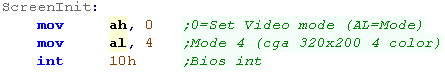
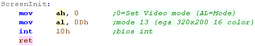
| We're going to use 320x200 4 color CGA mode in this tutorial ...
this is mode 4 To enable this we'll use Interrupt 10h (The BIOS interrupt) and function 0 (Set video Mode) We specify function 0 in AH - and mode 4 in AL before executing INT 10h |
 |
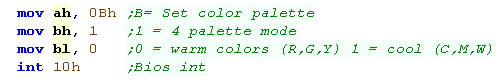
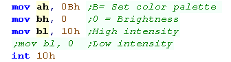
| We want to select our colors. We need INT 10h again We're going to use function 0Bh this time (Set Color Palette) We need to set BH=1 to select a palette... BL will choose the palette. BL=0 gives Black, Red,Green and Yellow BL=1 gives Black, Cyan,Magenta and White |
 |
| Although we have only two color options, we also have two
brightness' Again, we use INT 10h, but this time we use BH=0 BL should be set to 10h or 0h to set High brightness or Low brightness. |
 |
Calculating Screen Addresses
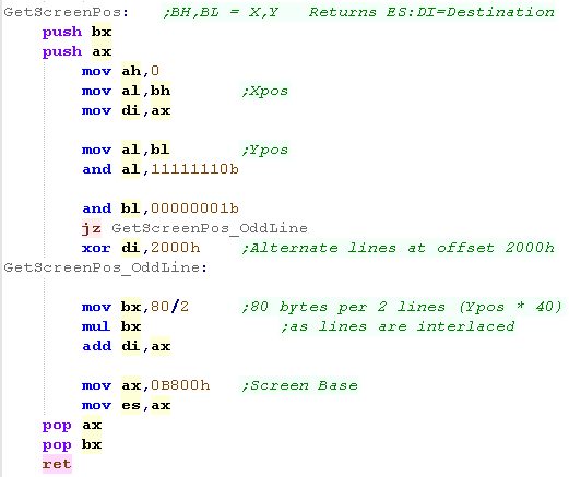
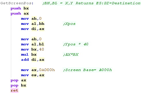
| The screen is 320x200, and each byte has 4 pixels
(in linear format - left 2 bits of a byte are leftmost pixel) So each line is 80 bytes... BUT the screen is interlaced! We need to set our segment to write to 0b800h Y Line 0 is at address offset &0000 Y Line 1 is at address offset &2000 Y Line 2 is at address offset &0040... and so on This GetScreenPos will take X,Y pos in BH,BL and return and address in ES:DI to write bitmap data to |
 |
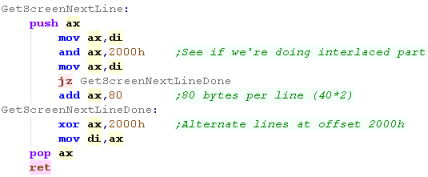
| When we want to move down a line, we also need to cope with the
interlacing effect |
 |
Showing a sprite
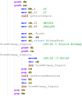
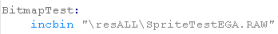
| We're going to include a bitmap file for our image | 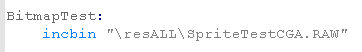 |
| We're going to use our GetScreenPos to calculate a starting
screen address, We'll use movsb to transfer bytes from the source to the destination. After each line, we'll use GetScreenNextLine to move down a line. |
 |
| Here are the 4 possible renders of the character, depending on
palette and brightness. Isn't CGA amazing!?.... ... (What do you mean 'no?') |
    |
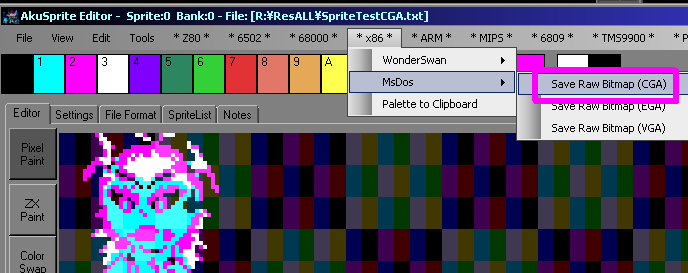
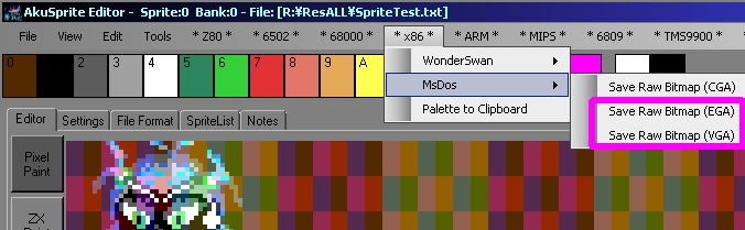
| If you want to create a valid bitmap file, try out my AkuSprite
Editor, it's free and open source. Use the "Save Raw Bitmap (CGA)" option from the x86->MS-DOS menu |
 |
 |
CGA
does support various other graphics modes, but we'll only be
covering 4 color for now - as it's the most memorable for it's
odd color scheme! We may look at the others later, if enough people are interested! |
| We're going to use 320x200 16 color EGA mode in this time ...
this is mode 13 (0Dh) To enable this we'll use Interrupt 10h (The BIOS interrupt) and function 0 (Set video Mode) We specify function 0 in AH - and mode 0Dh in AL before executing INT 10h |
 |
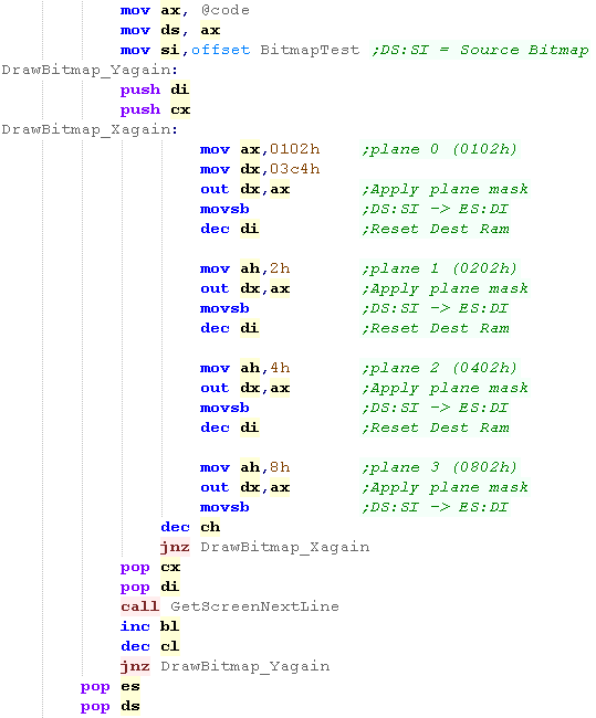
| The screen is 320x200, and each pixel needs 4
bits... but rather than these 4 bits being kept in a nibble, they
are stored in separate bitplanes. This means eight pixels of bit0 are in a single byte... eight bit1 's are in another... the same for bit2 and bit3 These bitplanes are paged in with OUT commands OUTing to port 03C4h (we'll see them later) for this reason, even though each line needs 160 bytes in each page the width is only 40 bytes The screen base is in segment A000h This GetScreenPos will take X,Y pos in BH,BL and return and address in ES:DI to write bitmap data to |
 |
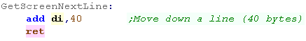
| When we want to move down a line, we just add 40 to the current
position |
 |
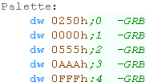
| In these tutorials we use a common palette format for all our
platforms, we then convert this to the format of the hardware. each channel uses a nibble - with one nibble unused. |
 |
||||||||||||||||
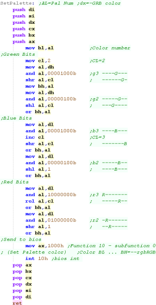
For EGA we need to convert this to a byte with bits in the
following format:
Each channel has 2 bits... R1/G1/B1 is the High bit... giving 2/3rds of the color value R0/G0/B0 is the low bit... giving 1/3rds of the color value We need to shift two bits from the palette definition into BH (in the correct positions) We then use function 10h (in AH), sub function 0 (in AL) and call INT 10h to set palette entry BL to color BH (in the bit definition above) |
 |
||||||||||||||||
| We'll apply the palette in our example | 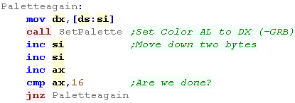 |
| The
EGA palette doesn't allow all combinations of these palette
bits, so some settings may not look as good as you hope... if
you want 'proper colors' take a look at VGA Fear not, we'll be looking at this next! |
 |

| If you want to create a valid bitmap file, try out my AkuSprite
Editor, it's free and open source. Use the "Save Raw Bitmap (EGA)" option from the x86->MS-DOS menu |
 |
| We're going to use 320x200 256 color VGA mode in this time ...
this is mode 19 (13h) To enable this we'll use Interrupt 10h (The BIOS interrupt) and function 0 (Set video Mode) We specify function 0 in AH - and mode 13h in AL before executing INT 10h |
 |
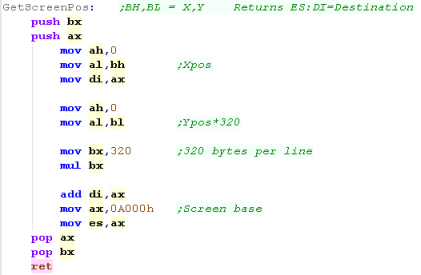
| The screen is 320x200, and each pixel needs a
whole byte! The screen base is in segment A000h Each line is 320 bytes wide, so we just multiply the Ypos by 320, and add the xpos (in bytes) This GetScreenPos will take X,Y pos in BH,BL and return and address in ES:DI to write bitmap data to |
 |
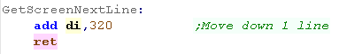
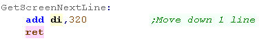
| When we want to move down a line, we just add 320 to the
current position |
 |
| In these tutorials we use a common palette format for all our
platforms, we then convert this to the format of the hardware. each channel uses a nibble - with one nibble unused. |
|
||||||||||
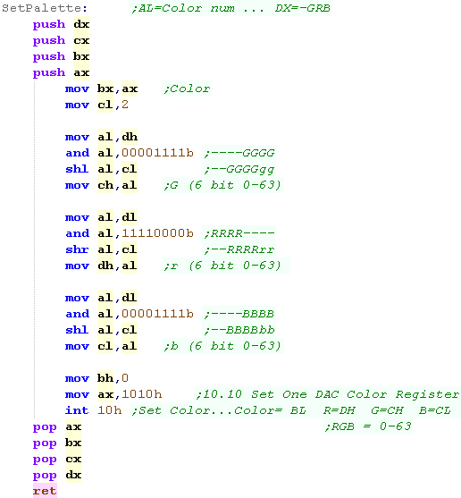
| For VGA we use the function 10h (in AH) subfunction 10h
(In AL) We use BL to select the palette entry we want to change... we use 6 bits to define the RGB component for each channel (top two bits unused) Each is stored in a different register.
As we only have 4 bits in our common format, we shift these bits to the top 4 of the 6 bit definition we then use INT 10h to define the palette |
 |
||||||||||
| We'll apply the palette in our example | |
| We're only using 4 bits of
the 6 possible for the VGA display color definitions! So we're not doing a great job... Sue me!... the priority with these tutorials is MULTIPLATFORM code... and these palette definitions are used on many other systems... If you prefer, just write your own code with 6 bit palette definitions and quit whining! |
 |
| We're going to include a bitmap file for our image | 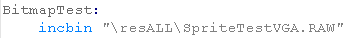 |
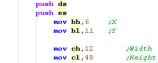
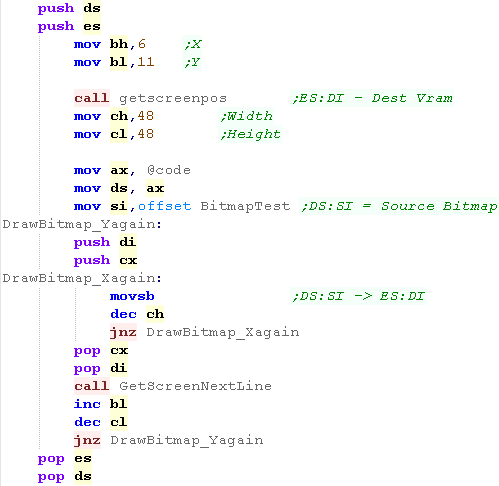
| We're going to use our GetScreenPos to calculate a starting
screen address, We'll use movsb to transfer byte each from the source to the destination... After each line, we'll use GetScreenNextLine to move down a line. |
 |
| Thanks to VGA, We can now enjoy the bitmap in it's authentic colors! |  |
| If you want to create a valid bitmap file, try out my AkuSprite
Editor, it's free and open source. Use the "Save Raw Bitmap (VGA)" option from the x86->MS-DOS menu |
|
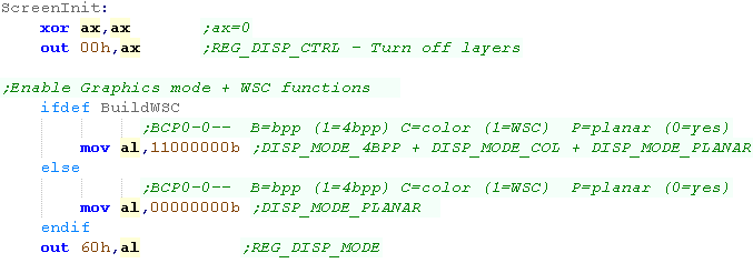
| First we're going to turn off the
screen layers - we do this with port 00h Next we use port 60h to set the display mode - and enable color functions on the WonderSwan Color. We're using 'Planar mode' in these tutorials, so graphics are in Bitplanes. |
 |
|
 |
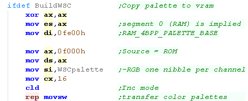
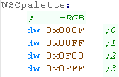
When we want to define our palette on the WonderSwan color
we need to write words to address FE00h in ram onwards Each color takes two bytes in the format 0-RGBh - where each channel uses a nibble of the word and one nibble is unused |
  |
 |
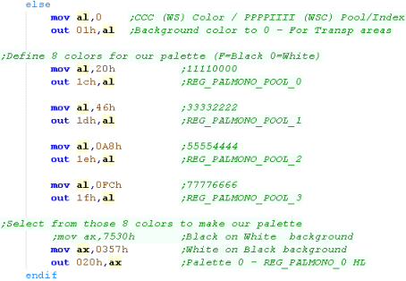
On the black and white WonderSwan, we define a pool of 8
colors with ports 1Ch / 1Dh / 1Eh /1Fh... Each Byte contains 2 colors - as each nibble is one color We then select 4 of these colors for Palette 0 - which we'll use for the tiles with port 20h |
 |
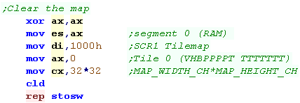
| OK, lets clear the tilemap! We needs to write 32 words to ram address 1000h... our tilemap is 32 * 32 |
 |
|
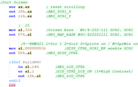
We need to set up our screen First we'll reset the tilemap position with port 10h,11h Next we define the memory address of the tilemaps with port 07h We'll enable the tilemap (SCR1) with port 00h Finally, on the WonderSwan Color, we'll enable High Contrast mode 14h (Though it may have no effect on the emulator?) |
 |
|
 |
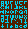
We're going to draw a 48
x 48 image onscreen, but we'll do it with the tile-map... To do this we need to split the pattern into 8x8 chunks, and fill a visible area of the screen with those tiles... Lets Learn how! |
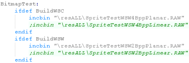
| We're going to define some tiles to draw our
image... we need them to be in the correct colordepth, (2bpp
for Wonderswan, 4bpp for Wonderswan color) We also need them to be in the format we selected during ScreenInit (these tutorials use PLANAR) |
 |
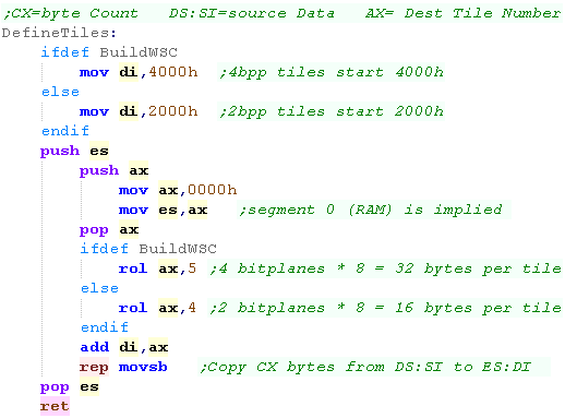
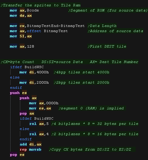
| We'll need to transfer these tiles to VRAM On the WonderSwan, tiles need to go to address 2000h - and each tile is 16 bytes, On the WonderSwan Color, tiles need to go to address 4000h - and each tile is 32 bytes, We'll use MOVSB to transfer bytes from DS:SI to ES:DI... REP tells the command to repeat CX times |
 |
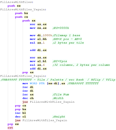
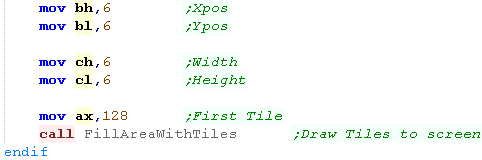
| We're going to need to fill a square area of the screen
with consecutive tile numbers to show our sprite. |
 |
| We're going to define a function called 'FillAreaWithTiles' The (Start X,Y) position will be passed in (BH,BL) The (Width,Height) will be in CH,CL) The first tile number will be in AX The Tilemap is stored at memory address 0000h and is 32x32 tiles in size. so our formula is: Tile Address = 1000h + (Ypos * 32 * 2) + (Xpos * 2) Each uses one word (Two Bytes) in the format: VHBPPPPT TTTTTTT V = V-flip H = H-flip B = wsc Bank P = Palette T = Tile |
 |
| First we need to transfer the patterns to vram. We'll use our DefineTiles function to do that. |
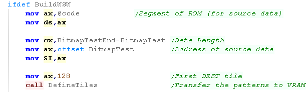 |
| Now our Tile patterns are in VRAM, we can show them on
screen, We use FillAreaWithTiles to do this. |
 |
| Here is the WonderSwan Color, and regular Wonderswan
version... |
  |
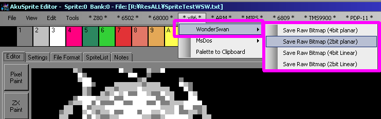
| If you want to create a valid bitmap file, try out my AkuSprite
Editor, it's free and open source. Use the "WonderSwan" options from the x86 menu |
 |
| We're going to use INT 16 to read the keyboard. There are 3 commands we'll be looking at - the 'command' is specified in AH. BUT there are 2 versions of these commands... the XT versions (for old keyboards) and AT versions which can read more keys... other than that they are basically the same. In all cases the result is returned in AX... the Z flag is also set depending on if a key was read by AH=01h |
|
||||||||||||||||||
The shift keys can be read while other keys are pressed... here
are the possible options:
|
|||||||||||||||||||
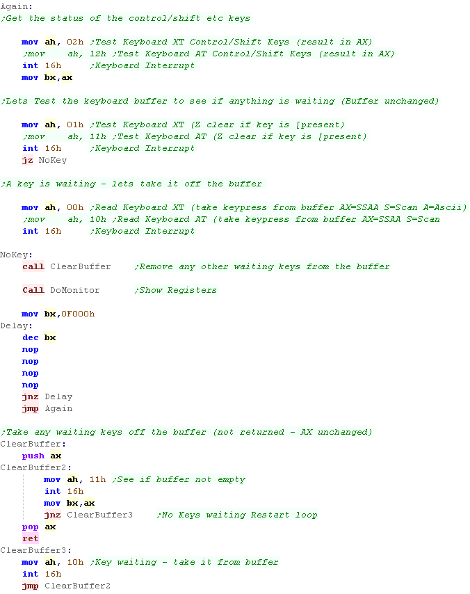
We will use 3 commands... AH=00h will read a key from the key buffer...but it will wait if no key is in the buffer, which isn't what we want. AH=01h will test the buffer, but doesn't empty it... we'll do that, and only use AH=00h when there is one (We need 00h to clear the buffer)... flag Z=true if no key is pressed AH=02h will test the shift buttons, this is instant and doesn't use the buffer. We've used this to read the keystate and show it with our monitor. We've also created a 'ClearBuffer' function which will read in any outstanding keys, and remove them from the buffer. |
 |
||||||||||||||||||
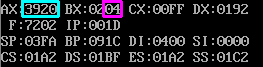
| Here BL has read in the control/shift keys...
04 means we had CTRL down AX is the key pressed (Space).... AL shows the ASCII for the pressed key... AH shows the 'keycode' The Ascii is affected by keys like CapsLock... the keycodes are not! |
 |
| In most cases
00h,01h and 02h are the same as 10h,11h and 12h - but there are
a few differences. F12 was added with the later keyboards... so cannot be read by 00h,01h and 02h! |
 |
| We can read in the cursors and some shifts and other keys, and
convert them into a 'bitmask'... we can then test this for
direction movement in a game. Here we're reading Up,Down,Left, and Right cursors... Space and Enter Each will set a bit of AL We're also loading shifts into AH |
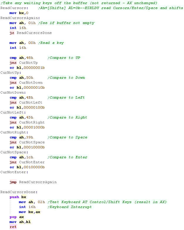 |
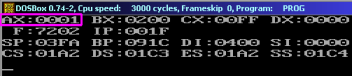
| Here UP was pressed, so bit 0 of AX is 1. if DOWN was pressed bit 1 would be 1... Left would be bit 2 and so on. |
 |
|
Joypad reading on the Wonderswan |
| The Wonderswan has two 4 direction Joypads (Pad X,Pad Y) two
Fire buttons (A and B) and a start button (Start!) The Wonderswan controls are controlled by port 0B5h We write to this port with one of the bits 4-6 set, then read back from the same port, bits 0-3 will be a pads directions or the buttons. |
|
|||||||||||||||||||||||||||||||||||||||||||||||||||||||||||||||
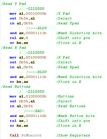
| Here we're reading in all the directions of both pads, and all
the buttons. These are loaded and combined into BX one bit per button in the format 0b----RLDU-BASRLDU |
 |
|||||||||||||||||||||||||||||||||||||||||||||||||||||||||||||||
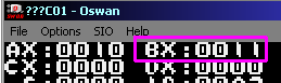
| The results are shown in BX, here Up+Start were pressed |
 |
 |
Joystick reading on MS-DOS via INT 15 |
| We can use INT 15h, function 84H to quickly read the joystick. We specify AH=84H to select the joystick function, and we specify the result we want in DX DX=0 will read the fire buttons of both joysticks into AL.... Bit 4,5 are Joystick 1... But 6,7 are Joystick 2 fires DX=1 will read the directions of both joysticks... Joy 1 (X,Y) is in (AX,BX)... Joy 2 (X,Y) is in (CX,DX) |
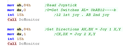 |
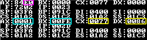
| In the first run, We've read in the Fire
Buttons into AL In the second run, We've read the Analog joystick position of Joy 1 into AX,BX... and Joy 2 into CX,DX |
 |
|
Joystick reading on MS-DOS via INT 15h |
| We can use INT 15h, function 84H to quickly read the joystick. We specify AH=84H to select the joystick function, and we specify the result we want in DX DX=0 will read the fire buttons of both joysticks into AL.... Bit 4,5 are Joystick 1... But 6,7 are Joystick 2 fires DX=1 will read the directions of both joysticks... Joy 1 (X,Y) is in (AX,BX)... Joy 2 (X,Y) is in (CX,DX) |
|
| In the first run, We've read in the Fire
Buttons into AL In the second run, We've read the Analog joystick position of Joy 1 into AX,BX... and Joy 2 into CX,DX |
|
| Reading the joystick with INT 15h is easy but
boring! Because we enjoy pain(!), lets learn how to read directly from the hardware with Port 201h!!! |
|
|
Joystick reading on MS-DOS via Port 201h |
| We can read in both joysticks from a single port - Port 201h! The two fires of each joystick are represented by a bit... and each direction has a single bit. But the joysticks are Analog!... how do we get an analog value from a single bit? Well we strobe the port, and count how long it takes for the bit to change to zero - that 'count' is our X or Y position. |
Port 201h
Joystick 1 - Joystick 2 |
||||||||||||||||||
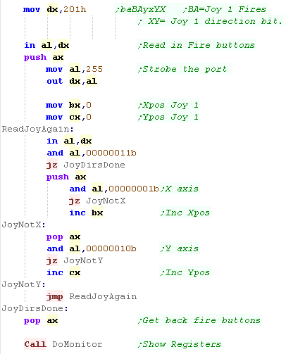
| Here is a sample routine to read from Joystick 1. First we read IN from port 201h to get the Fire buttons. Next we need to strobe port 201h... we OUT 255 to this port (apparently this charges the capacitors!?) Now we read in from the port, We INC BX until Bit 0 reaches zero (the X pos) We INC CX until Bit 1 reaches zero (the Y pos) Of course we could do the same with Bit 2,3 for Joystick 2 if we wished |
 |
||||||||||||||||||
| In this example AL has the joystick buttons...
BX is the X-pos, and CX is
the Y-pos Here we had Left pressed and one fire button. |
|
|
Here we've learned how to
read in 2 button joystick... But what about 4 or 6 button non
USB joysticks? Well... there are none!... I mean, they CHEAT, a 4 button joystick will use Fire 1/2 of Joy 2... and a 6 button joystick will use the X/Y axis of Joy 2 as two extra buttons - so you couldn't connect two 4 button pads in the DOS days!... Bet you appreciate USB more now eh? |
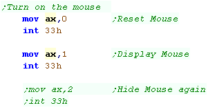
| We control the mouse with INT 10H... this takes a parameter in
AX AX=0 will reset the mouse to default settings AX=1 will display a hardware cursor... (the mouse works with it off too though!) AX=2 will turn off the hardware cursor again! |
 |
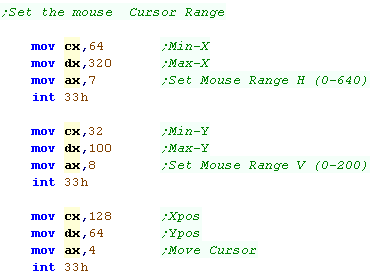
| If we want to control the range of mouse movement we can specify
a range of screen co-ordinates, the mouse cursor will be limited
to this range. We specify the Horizontal range with AX=7... the range is CX-DX We specify the Vertical range with AX=8... the range is CX-DX We can move the mouse cursor to a particular position with AX=4... The (X,Y) pos is in (CX,DX) |
 |
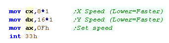
| We can alter the mouse speed with AX=0Fh - we pass an (X,Y)
speed in (CX,DX) Mouse co-ordinates are mesured in 'mickeys' because apparently someone thought that was funny! the Default speed is 8x16 mickeys... a higher value |
 |
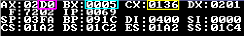
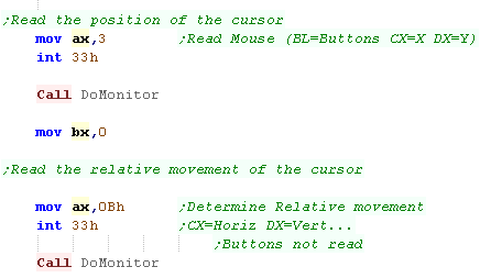
| We can read the X,Y position of the cursor, and the Mouse
buttons with AX=3h The (X,Y) Cursor position will be returned in (CX,DX)... the mouse buttons will be returned in BL in the format 0b-----CRL We can read in the relative move of the mouse with AX=0Bh... this returns an (X,Y) movement size in (CX,DX) it does NOT return the buttons in BL The relative movement returns how much the mouse moved, so 0,0 means the mouse has not changed... Note: AX=0Bh will return movement even if the cursor didn't move because it's already at the extremity of the screen. |
 |
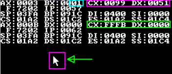
| First we loaded the Cursor position in CX,DX...
we also loaded the Mouse buttons in BL (Left
Mouse was pressed) Then we loaded the relative movement in CX,DX... the mouse was moving Left, so CX is negative. |
 |
| If
you're looking to make a point and click adventure you'll
probably want to use AX=3 to do
the cursor with screen limits... If you're trying to make Wolfystine 3B, then you'll want to use AX=0Bh, so the player can keep turning round and round! |
|
| Since the earliest of my tutorials,
I've handled sound with a simple sound driver knows as
'ChibiSound' This takes an 8 bit byte value from 0-255, and make a sound of selectable pitch, with noise or half volume in a similar way on all our systems! This was created for Grime Z80, and allows common sound code to give similar effects on all the systems! All we do is load the AL register with a value, and call ChibiSound! Of course, this won't be enough to make music (please wait for ChibiSound Pro - yes really!) but it will give us some simple SFX, and make it easy to compare doing simple tasks on our various systems! |
|
| Port | Modes | Purpose | Bits | Notes |
| 0040 | RW | PIT counter 0, counter divisor (XT, AT, PS/2) | CCCCCCCC | Send L/H Pair |
| 0041 | RW | PIT counter 1, RAM refresh counter (XT, AT) | CCCCCCCC | Send L/H Pair |
| 0042 | RW | PIT counter 2, cassette & speaker (XT, AT, PS/2) | CCCCCCCC | Send L/H Pair |
| 0043 | RW | PIT mode port, control word register for counters 0-2 | CCAAMMMS | C=Counter select (0-2), A=counter Access, M=counter Mode (0-5), S=counter Style (0=16 bit 1=BCD) |
| 0061 | W | PPI Programmable Peripheral Interface 8255 (XT only) | ----PPST | P= parity checks S=Speaker enable T=speaker Timer enable |
| 0061 | R | KB controller port B control register (ISA, EISA) | EETDPPST | E=errors T=Timer D=Detect P= parity checks S=Speaker enable T=speaker Timer enable |
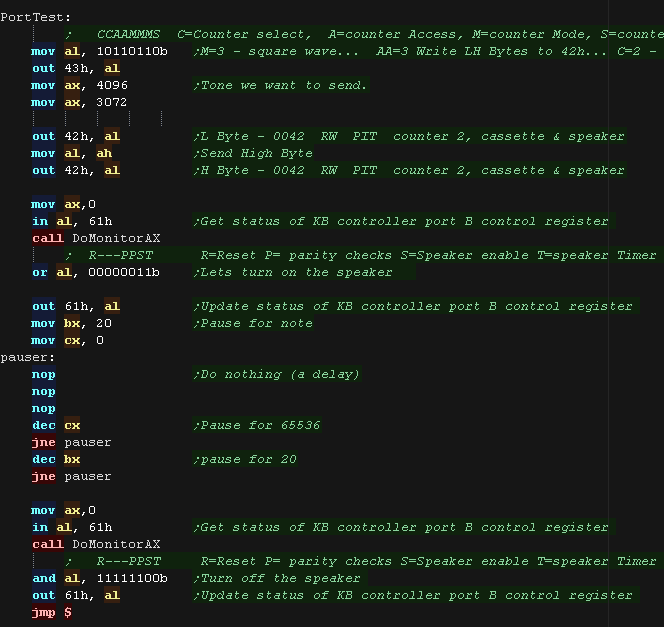
| Here is a simple sound example we saw in 8086 Lesson 6. Here we set up the timer with port 43h, selecting Counter 2 and the counter mode. Next we write a 16 bit value in two bytes to 42h, we write the Low byte first, then the High one We turn on, or off the speaker with a write to bit 1 of port 61h |
 |
Writing ChibiSound
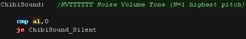
| First we check if AL=0, if it is, we need to turn off the sound,
we'll see the code to do this in a moment. |
 |
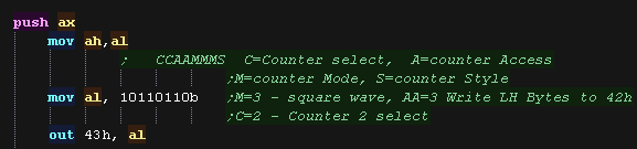
| First we'll set up the sound with port 43h, we're going to use
Counter 2 to define the pitch, and Mode 3, which will make a
square wave. |
 |
| OK... lets set our pitch, we need to take the 6 'pitch bits' of our parameter, and shift them into the right position of our 16 bit value, we then send these two bytes to 42h | 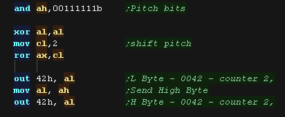 |
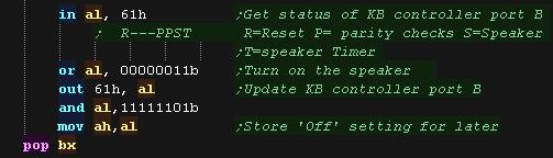
| Next we need to turn on the speaker, we need to write a 1 to bit
1 of 61h to turn the sound on, and bit 0 to enable the timer. |
 |
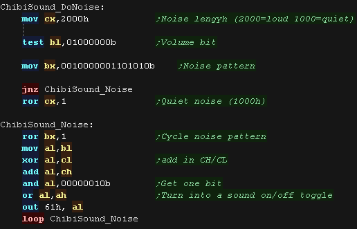
| We can't really set the volume of the speaker, but we can make a
short tone if the volume bit of our parameter is zero, we also need to handle the noise effect. If the noise is disabled and we want a quiet tone, we wait a while with the tone on, and turn the speaker off. |
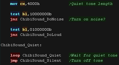 |
| If the noise is enabled we'll 'randomly' turn the speaker on and
off... we'll have a noise pattern in BX, and use this as a mask,
with the bytes of our counter to make a noise effect. |
 |
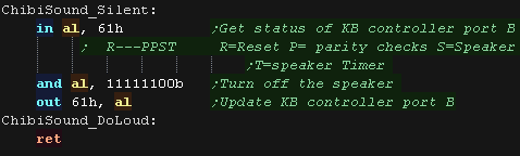
| We can silence the sound by setting bit 1 of port 61h to zero. |
 |
 |
The
Beeper speaker sucks pretty hard, but fear not! We'll have a look later at the Soundblaster/AY... which kicks far more audio ass! Here' comes the noise! |
The ADLIB sound card usesd OPL2, which is also supported by the full SoundBlaster range, it uses a range of registers to make its sounds, each sound channel is formed by a combination of two Operators
NOTE: OPL3 doubled the number of registers, with an 'Advanced' set... for simplicity (and my sanity) we'll just be covering the basic OPL2 set, which are supported by OPL3 as well!
There are a total of up to 9 sound channels... each sound is
the combination of two "OP signals"... we should set both to get a
sound from a channel! How the OPs are combined is defined by bit 0
of registers C0h-C8h... see the pdf documents for more info.
| Channel Signal | 1 | 2 | 3 | 4 | 5 | 6 | 7 (Ryt) |
8 (Ryt) |
9 (Ryt) |
|||||||||
| OP1 Slot 1 Signal | 1 | 2 | 3 | 7 | 8 | 9 | 13 | 14 | 15 | |||||||||
| OP2 Slot 2 Signal | 4 | 5 | 6 | 10 | 11 | 12 | 16 | 17 | 18 | |||||||||
| Register settings for slot |
20 | 21 | 22 | 28 | 29 | 2A | 30 | 31 | 32 | |||||||||
| 23 | 24 | 25 | 2B | 2C | 2D | 33 | 34 | 35 | ||||||||||
| 40 | 41 | 42 | 48 | 49 | 4A | 50 | 51 | 52 | ||||||||||
| 43 | 44 | 45 | 4B | 4C | 4D | 53 | 54 | 55 | ||||||||||
| 60 | 61 | 62 | 68 | 69 | 6A | 70 | 71 | 72 | ||||||||||
| 63 | 64 | 65 | 6B | 6C | 6D | 73 | 74 | 75 | ||||||||||
| 80 | 81 | 82 | 88 | 89 | 8A | 90 | 91 | 92 | ||||||||||
| 83 | 84 | 85 | 8B | 8C | 8D | 93 | 94 | 95 | ||||||||||
| E0 | E1 | E2 | E8 | E9 | EA | F0 | F1 | F2 | ||||||||||
| E3 | E4 | E5 | EB | EC | ED | F3 | F4 | F5 | ||||||||||
| Register settings for the channel |
A0 | A1 | A2 | A3 | A4 | A5 | A6 | A7 | A8 | |||||||||
| B0 | B1 | B2 | B3 | B4 | B5 | B6 | B7 | B8 | ||||||||||
| C0 | C1 | C2 | C3 | C4 | C5 | C6 | C7 | C8 | ||||||||||
Channels 7,8,9 can be toggled as Rhythm effects by setting bit 5 of 0BDh to 1
In this mode bits 0-4 of 0BDh will 'fire' the effects... each
effect uses some of the signal slots, the registers for this slot
will need to be set up as usual
BDh bits %DDRBSTCH
R=Rhythm enabled (channel 7-9 no longer normal FM sound)
| Bit / Rhythm sound |
OP / Signal Slots used |
| B=Bass | 13 & 16 |
| S=Snare | 17 |
| T=Tom | 15 |
| C=Cymbal | 18 |
| H=Hihat | 14 |
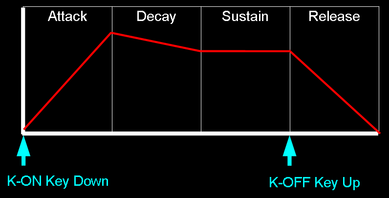
Sound over time
The OPs define how the sound level changes over time... K-On and K-Off mimic the way piano keys work.. when the key is struck the sound will start (Attack), and fade slowly (Decay) to a constant tone (Sustain), when the key is lifted, it will fade quickly (Release)
Adlib OPL2 Registers and bits
| Register | Details | Bits | Details |
| 01h | Test | --WDDDDD | W=Wave select Enable (opl2) / D=Test Data |
| 02h | Timer 1 Setting 80-20.4us | TTTTTTTT | T=Timer |
| 03h | Timer 2 Setting 320-82 us | TTTTTTTT | T=Timer |
| 04h | Timer 1/2 control | RMM---SS | R=Reset M=Mask S=? |
| 08h | Speech Synth / Keyboard Split NoteSel | CS------ | C=CSM Speech synth mode / S=note Select |
| 20h - 35h | Multi / Key Scale Rate / EG-Type Tone / Vibrato / AM modulation | AVEKMMMM | A=AM V=VIB E=EG-Typ K=KSR M=Multiple |
| 40h - 55h | Total Level / Key Scale Level | KKTTTTTT | K=KeyScaleLevel T=Total Level (0=loud) |
| 60h - 75h | Decay Rate / Attack Rate | AAAADDDD | A=Attack (0=slow) D=Decay (0=slow) |
| 88h - 95h | Release Rate / Sustain Level | SSSSRRRR | S=Sustain (0=loud) R=Release (0=slow) |
| A0h - A8h | F number | FFFFFFFF | F=Fnumber L |
| B0h - B8h | Block / K-ON | --KBBBFF | F=Fnumber H B=Block K=K-on |
| BDh | Rhythm mode (Chn 7-9) / Vibrato Depth / AM Depth | DDRBSTCH | D=Depth
(AM/VIB) R=Rhythm B=Bass(13,16) S=Snare(17) T=Tom(15) C=Cymbal(18) H=Hihat(14) |
| C0h - C8h | FeedBack factor / C=Connection sine/fm | ----FFFC | F=Feedback
C=Connection (Op combination mode) |
| E0h - F5h | Wave Select | ------WW | WW=Wave Select |
| (Address port Read) | Status Reg | IFF----- | I=IRQ F=Flag |
Useful ADLIB docs:
yamaha_ymf262
- OPL3 Manual (Adlib Gold / SB16)
YM3812 - OPL2
Manual (adlib)
ym3625 -
OPL(1) manual
Soundblaster -
Soundblaster programming guide
Adlib
Programming - Adlib programming guide
Coding up some sound!
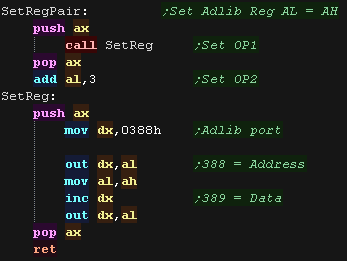
| We'll need to set the Adlib registers, and we'll create a
'SetReg' function to do this... it will set adlib register AL to
value AH When setting the OP Regs 20h-F5h, we'll often want to set OP1 and OP2 to the same value... we'll create a 'SetRegPair' to do this too! |
 |
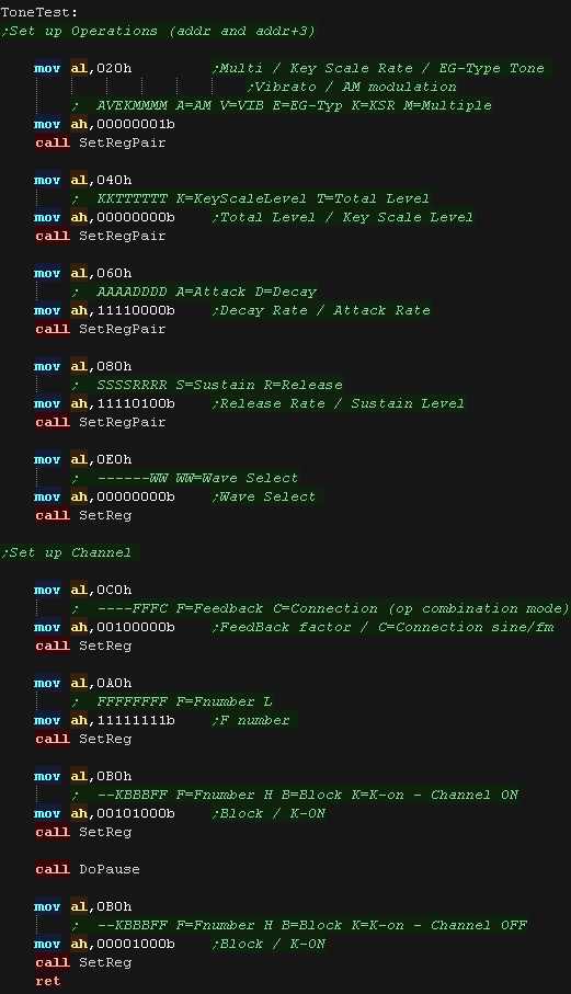
| Yo make a tone we need to set up the operations for the tone -
we set OP1 and OP2 to the same values with SetRegPair we set the pitch with 0A0h/0B0h we turn the tone on with K-ON=1 (bit 5 of 0B0h), wait a while with 'DoPause' and turn it off with K-ON=0 |
 |
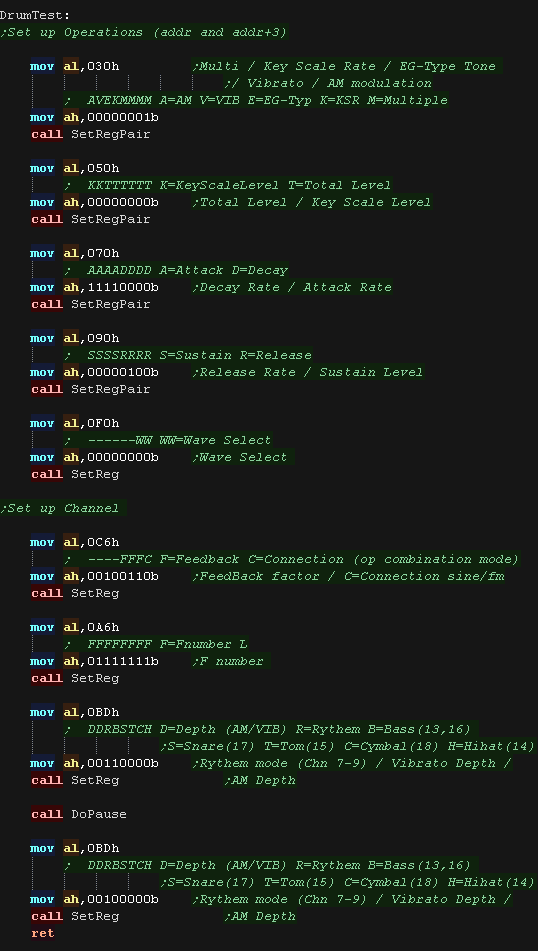
| We can use some of the channels for Rhythm effects! - we need
to turn this function on with bit 5 of 0BDh We then enable the individual effects with bits 0-4 of 0BDh We need to set the matching OP and channel settings for the sound being made. |
 |
| Since the earliest of my
tutorials, I've handled sound with a simple sound driver knows
as 'ChibiSound' This takes an 8 bit byte value from 0-255, and make a sound of selectable pitch, with noise or half volume in a similar way on all our systems! This was created for Grime Z80, and allows common sound code to give similar effects on all the systems! All we do is load the AL register with a value, and call ChibiSound! Of course, this won't be enough to make music (please wait for ChibiSound Pro - yes really!) but it will give us some simple SFX, and make it easy to compare doing simple tasks on our various systems! |
|
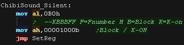
| First we check if AL=0, if it is, we need to turn off the
sound. To turn off the sound we release K-ON for the channel with reg B0h |
 |
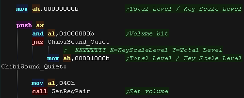
| We'll use the one volume bit from the chibisound parameter to
set the volume We set the volume with reg 040h - Zero is loudest! |
 |
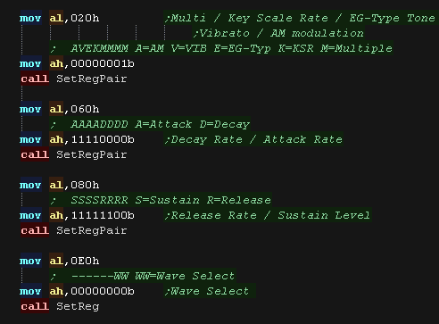
| We need to set up a few other registers, or we won't get a
tone at all! We want a tone that starts quickly (Fast Attack) and stops quickly (Fast Release) |
 |
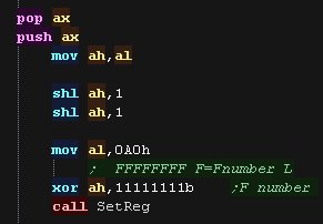
| Next we Set the pitch... we have 6 bits of pitch setting in
our ChibiSound byte. |
 |
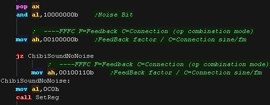
| Depending on if we want noise or not, we set bits 1-3 of
0C0h.... these are the feedback bits. |
 |
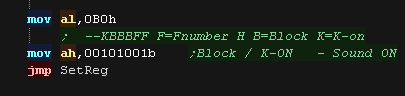
| Finally we need to enable K-ON to turn on the sound |
 |
| We've learned how to make
some simple sounds! If you want something more impressive, download the examples, and try out some different settings to make something more musical! |
|
Setting up hardware sprites
| We're going to make a version of our Joystick example that moves a smiley sprite around the screen. |  |
| The Wonderswan uses the same tilepatterns for it's Tilemap as its
sprites, so we can use the same code as we've used before. Here we're loading our test sprites to tile 128+ |
 |
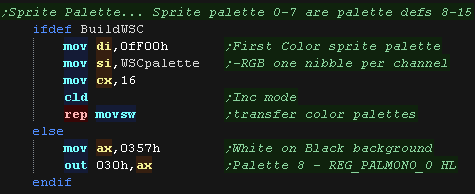
| When we define a sprite we set it's palette as numbers 0-7, but
these actually map to palettes 8-15, so we need to set these with
the colors we want. |
 |
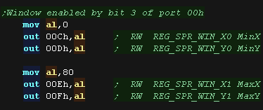
| We can define a window... this allows us to 'mask' sprites to an
area. Here we define a window of (0,0)-(80,80) We need to turn on the window with bit 3 of port 00h, we can then set each sprite to appear 'inside' or 'outside' the window with bit 12 of the individual sprite definition |
 |
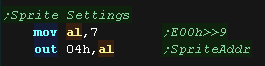
| Part of our normal ram will be transferred automatically to the
hardware by a DMA, we need to specify the address of our sprite
table with port 04h We need to bitshift the address we want to use right by 9 bits... so if we want to use address 0E00h, we write a 7 to port 04h (0e00h>>9 = 7) |
 |
| We need to set bit 2 of port 00h to turn on the sprites... we also set bit 3 if we want to enable the window. | 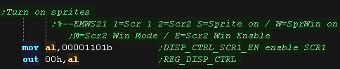 |
Setting a sprite
Sprites
are controlled by a set of registers, and 4 bytes per entry in the table
at address defined by port 04h. There are 128 in total.
Each sprite uses 4 bytes in the format: %XXXXXXXXYYYYYYYYVHPWpppnnnnnnnnn N=tile Number V=Vflip H=Hflip P=Priority W=Window p=Palette(8+) Y=(-8 to 144) X=(-8 to 224)
The window can be enabled or disabled by port 00h, and how the window affects the sprites is defined by bit 12 of the sprite definitions in ram. We need to define the first used sprite with port 05h, and the sprite count with 06h
If we set the base of the tile ram to 0E00h, the memory addresses that define each sprite will be as shown below.
| Address | Sprite | Bits | Details |
| 0E00 | 0 | NNNNNNNN | N=tile Number |
| 0E01 | 0 | VHPWpppN | N=tile Number V=Vflip H=Hflip P=Priority W=Window (0=in 1=out) p=Palette(8+) |
| 0E02 | 0 | YYYYYYYY | Y=(-8 to 144) |
| 0E03 | 0 | XXXXXXXX | X=(-8 to 224) |
| 0E04 | 1 | NNNNNNNN | N=tile Number |
| 0E05 | 1 | VHPWpppN | N=tile Number V=Vflip H=Hflip P=Priority W=Window (0=in 1=out) p=Palette(8+) |
| 0E06 | 1 | YYYYYYYY | Y=(-8 to 144) |
| 0E07 | 1 | XXXXXXXX | X=(-8 to 224) |
| 0E08 | 2 | NNNNNNNN | N=tile Number |
| 0E09 | 2 | VHPWpppN | N=tile Number V=Vflip H=Hflip P=Priority W=Window (0=in 1=out) p=Palette(8+) |
| 0E0A | 2 | YYYYYYYY | Y=(-8 to 144) |
| 0E0B | 2 | XXXXXXXX | X=(-8 to 224) |
| � | � | � | � |
| 0FFC | 127 | NNNNNNNN | N=tile Number |
| FFFD | 127 | VHPWpppN | N=tile Number V=Vflip H=Hflip P=Priority W=Window (0=in 1=out) p=Palette(8+) |
| FFFE | 127 | YYYYYYYY | Y=(-8 to 144) |
| FFFF | 127 | XXXXXXXX | X=(-8 to 224) |
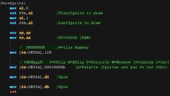
| We need to define the first used sprite with
port 05h, and the sprite
count with port 06h. We need to then set up the 4 bytes that position the sprite and set it's tile and palette. |
 |
| Sprites
use the same pattern data and format as tiles so are only 8x8...
if we want 'big sprites' we'll have position lots of sprites
together. |
|
| View Options |
| Default Dark |
| Simple (Hide this menu) |
| Print Mode (white background) |
| Top Menu |
| ***Main Menu*** |
| Youtube channel |
| Patreon |
| Introduction to Assembly (Basics for absolute beginners) |
| Amazon Affiliate Link |
| AkuSprite Editor |
| ChibiTracker |
| Dec/Bin/Hex/Oct/Ascii Table |
| Alt Tech |
| Archive.org |
| Bitchute |
| Odysee |
| Rumble |
| DailyMotion |
| Please note: I wlll upload more content to these alt platforms based on the views they bring in |
| 68000 Content |
| ***68000 Tutorial List*** |
Learn 68000 Assembly  |
| Hello World Series |
| Platform Specific Series |
| Simple Samples |
| Grime 68000 |
| 68000 Downloads |
| 68000 Cheatsheet |
| Sources.7z |
| DevTools kit |
| 68000 Platforms |
| Amiga 500 |
| Atari ST |
| Neo Geo |
| Sega Genesis / Mega Drive |
| Sinclair QL |
| X68000 (Sharp x68k) |
| 8086 Content |
| Learn 8086 Assembly |
| Platform Specific Series |
| Hello World Series |
| Simple Samples |
| 8086 Downloads |
| 8086 Cheatsheet |
| Sources.7z |
| DevTools kit |
| 8086 Platforms |
| Wonderswan |
| MsDos |
| ARM Content |
| Learn ARM Assembly |
| Learn ARM Thumb Assembly |
| Platform Specific Series |
| Hello World |
| Simple Samples |
| ARM Downloads |
| ARM Cheatsheet |
| Sources.7z |
| DevTools kit |
| ARM Platforms |
| Gameboy Advance |
| Nintendo DS |
| Risc Os |
| Risc-V Content |
| Learn Risc-V Assembly |
| Risc-V Downloads |
| Risc-V Cheatsheet |
| Sources.7z |
| DevTools kit |
| MIPS Content |
| Learn Risc-V Assembly |
| Platform Specific Series |
| Hello World |
| Simple Samples |
| MIPS Downloads |
| MIPS Cheatsheet |
| Sources.7z |
| DevTools kit |
| MIPS Platforms |
| Playstation |
| N64 |
| PDP-11 Content |
| Learn PDP-11 Assembly |
| Platform Specific Series |
| Simple Samples |
| PDP-11 Downloads |
| PDP-11 Cheatsheet |
| Sources.7z |
| DevTools kit |
| PDP-11 Platforms |
| PDP-11 |
| UKNC |
| TMS9900 Content |
| Learn TMS9900 Assembly |
| Platform Specific Series |
| Hello World |
| TMS9900 Downloads |
| TMS9900 Cheatsheet |
| Sources.7z |
| DevTools kit |
| TMS9900 Platforms |
| Ti 99 |
| 6809 Content |
| Learn 6809 Assembly |
| Learn 6309 Assembly |
| Platform Specific Series |
| Hello World Series |
| Simple Samples |
| 6809 Downloads |
| 6809/6309 Cheatsheet |
| Sources.7z |
| DevTools kit |
| 6809 Platforms |
| Dragon 32/Tandy Coco |
| Fujitsu FM7 |
| TRS-80 Coco 3 |
| Vectrex |
| 65816 Content |
| Learn 65816 Assembly |
| Hello World |
| Simple Samples |
| 65816 Downloads |
| 65816 Cheatsheet |
| Sources.7z |
| DevTools kit |
| 65816 Platforms |
| SNES |
| eZ80 Content |
| Learn eZ80 Assembly |
| Platform Specific Series |
| eZ80 Downloads |
| eZ80 Cheatsheet |
| Sources.7z |
| DevTools kit |
| eZ80 Platforms |
| Ti84 PCE |
| IBM370 Content |
| Learn IBM370 Assembly |
| Simple Samples |
| IBM370 Downloads |
| IBM370 Cheatsheet |
| Sources.7z |
| DevTools kit |
| Super-H Content |
| Learn SH2 Assembly |
| Hello World Series |
| Simple Samples |
| SH2 Downloads |
| SH2 Cheatsheet |
| Sources.7z |
| DevTools kit |
| SH2 Platforms |
| 32x |
| Saturn |
| PowerPC Content |
| Learn PowerPC Assembly |
| Hello World Series |
| Simple Samples |
| PowerPC Downloads |
| PowerPC Cheatsheet |
| Sources.7z |
| DevTools kit |
| PowerPC Platforms |
| Gamecube |
| Work in Progress |
| ChibiAndroids |
| Misc bits |
| Ruby programming |
Buy my Assembly programming book
on Amazon in Print or Kindle!


Available worldwide!
Search 'ChibiAkumas' on
your local Amazon website!
Click here for more info!


Buy my Assembly programming book
on Amazon in Print or Kindle!
Available worldwide!
Search 'ChibiAkumas' on
your local Amazon website!
Click here for more info!
Buy my Assembly programming book
on Amazon in Print or Kindle!
Available worldwide!
Search 'ChibiAkumas' on
your local Amazon website!
Click here for more info!
Buy my Assembly programming book
on Amazon in Print or Kindle!
Available worldwide!
Search 'ChibiAkumas' on
your local Amazon website!
Click here for more info!
Buy my Assembly programming book
on Amazon in Print or Kindle!
Available worldwide!
Search 'ChibiAkumas' on
your local Amazon website!
Click here for more info!
Buy my Assembly programming book
on Amazon in Print or Kindle!
Available worldwide!
Search 'ChibiAkumas' on
your local Amazon website!
Click here for more info!
Buy my Assembly programming book
on Amazon in Print or Kindle!
Available worldwide!
Search 'ChibiAkumas' on
your local Amazon website!
Click here for more info!