| In theory the Gamecube has a 640x480 display, however it only
uses 4 bytes for every 2 pixels.
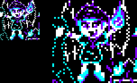
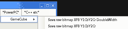
The gamecube uses a 'YUV' type display, where each pixel has a 8 bit brightness byte, but the color bytes are shared by neighboring pixels. Take a look at the images on the left... The small image was drawn at 1x, the one on the right is 2x... The colors on the left hand image are different in places, because of the shared color information. However If we treat the gamecube screen as 320x240, or 320x640 - halving the X axis, we can write the same color pixel to 4 bytes, and get the 'actual' colors we wanted! |
 |
MRGB-> YBR color
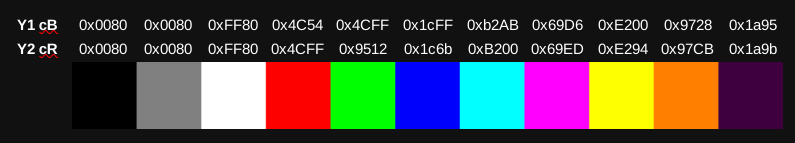
There's no way around itWe will need to convert our 24 bit RGB colors into the format for the Gamecube screen!
Color in RGB:Need help with your color maths??? I have a spreadsheet I used for the color conversions!
Download my 'Color conversion spreadsheet'
| We're gong to show a simple hello world message to the screen! | 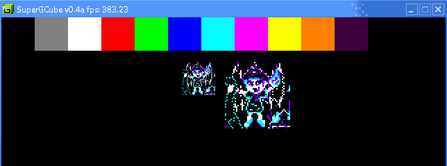 |
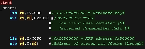
| We're going to use ELF2DOL to convert our program into a DOL
binary (It attaches a 256 byte header) We put our code in the '.text' section We need to set the address of our VRAM We're using 0xC0500000 for VRAM - the uncached version of 0x00500000 We write the address to the register 0xCC00201C (TFBL - Top Field Base Register (L) ) |
 |
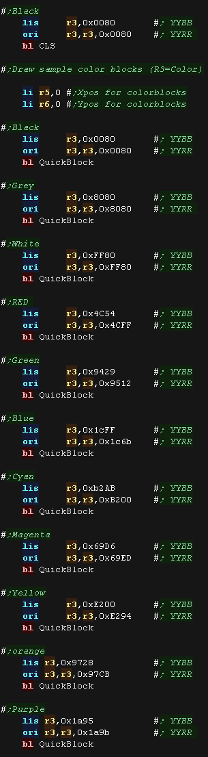
We need to clear our screen with CLS ! We load the Color word into R3 - in this case black. We then use QuickBlock to draw a 48x48 color block to test each color. |
 |
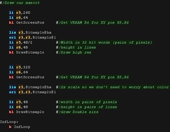
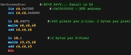
| We have a 'GetScreenPos' routine to convert an X,Y co-ordinate
into a VRAM destination We use DrawBitmap1x to draw the small bitmap, Due to the way the GameCube shares colors between pixels there will be some color distortion. We use DrawBitmap2x to draw the doublesize version, This version uses 2x2 scaled pixels, so each 'pixel' will have its own unique color. |
 |
| Clearing the screen is easy, we just wipe all 0x25800 thirty two bit words of VRAM from address 0xC0500000 onwards | 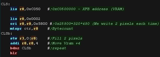 |
| The VRAM base is 0xC0500000, Each line of the screen is 640 pixels, and each pixel is 2 bytes. We multiply our X and Y pos to get the vram destination |
 |
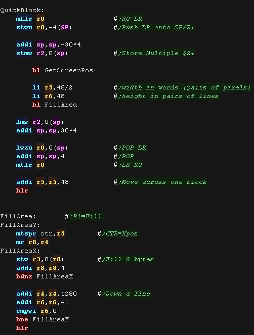
| The QuickBlock routine draws one of the test color
blocks. it just fills a square area with the same 32 bit value, then moves across the screen 48 pixels |
 |
| We include the two bitmap files we want to draw as binary files. | 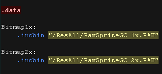 |
| My Akusprite editor allows for export in the format used by the
gamecube, and offers the 'DoubleWidth' export for the 2x file used
in this example. Akusprite editor is included in the downloads. |
 |
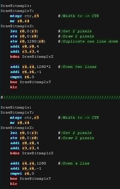
| We have 2 draw routines, though both are virtually identical. We store the Width in the CTR register. We read 2 pixels (32 bits) from the source (R3) and draw them to the screen (R8) The 2x source file has each pixel doubled horizontally in the file, but to double vertically we draw the same data one line down (offset 1280) |
 |
 |
These simple tutorials always use a single ASM
file. This time is slightly different, it's a single ASM file, but by enabling ".equ showtext,1" the joypad output will be shown to the screen - this extra function requires a couple of extra ASM files, but is totally optional. |
| Port |
Purpose |
Bits |
Notes |
| 0xCC006400 | SIC0OUTBUF - SI Channel 0 Output Buffer (Joy-channel 1 Command) | %--------CCCCCCCC0000000011111111 | C=Command 0=Output0 1=Output1 |
| 0xCC006404 | Joy-channel 1 Buttons 1 | %---syxba--lrUDRLXXXXXXXXYYYYYYYY | |
| 0xCC006408 | Joy-channel 1 Buttons 2 | %XXXXXXXXYYYYYYYYLLLLLLLLRRRRRRRR | |
| 0xCC00640C | SIC1OUTBUF - SI Channel 1 Output Buffer (Joy-channel 2 Command) | %--------CCCCCCCC0000000011111111 | C=Command 0=Output0 1=Output1 |
| 0xCC006410 | SIC1INBUFH - SI Channel 1 Input Buffer High (Joy-channel 2 Buttons 1) | %---syxba--lrUDRLXXXXXXXXYYYYYYYY | |
| 0xCC006414 | Joy-channel 2 Buttons 2 | %XXXXXXXXYYYYYYYYLLLLLLLLRRRRRRRR | |
| 0xCC006418 | SIC2OUTBUF - SI Channel 2 Output Buffer (Joy-channel 3 Command) | %--------CCCCCCCC0000000011111111 | C=Command 0=Output0 1=Output1 |
| 0xCC00641C | Joy-channel 3 Buttons 1 | %---syxba--lrUDRLXXXXXXXXYYYYYYYY | |
| 0xCC006420 | Joy-channel 3 Buttons 2 | %XXXXXXXXYYYYYYYYLLLLLLLLRRRRRRRR | |
| 0xCC006424 | SIC3OUTBUF - SI Channel 3 Output Buffer (Joy-channel 4 Command) | %--------CCCCCCCC0000000011111111 | C=Command 0=Output0 1=Output1 |
| 0xCC006428 | Joy-channel 4 Buttons 1 | %---syxba--lrUDRLXXXXXXXXYYYYYYYY | |
| 0xCC00642C | SIC3INBUFL - SI Channel 3 Input Buffer Low (Joy-channel 4 Buttons 2) | %XXXXXXXXYYYYYYYYLLLLLLLLRRRRRRRR | |
| 0xCC006430 | SIPOLL - SI Poll Register (Joy-channel Control (?) (Calibration gun ?)) | %------XXXXXXXXXXYYYYYYYYEEEEVVVV | V=Vlbank copy E=Enable port Y=Ytimes X7 X lines |
| 0xCC006434 | SICOMCSR - SI Communication Control Status Register (command) | %r?--?ccs-mmmmmmm-nnnnnnneb-----? | R=Clear Transfer complete interrupt status |
| 0xCC006438 | SISR - SI Status Register (channel select & status2) | ||
| 0xCC00643C | SIEXILK - SI EXI Clock Lock | ||
| 0xCC006480 | SI I/O buffer (access by word) |
| Reading the joypad
in this example is based on the documentation in: YAGCD - Yet Another Gamecube Documentation Unfortunately, it's not clear that the INIT commands is having any effect (the example works without them) It's possible (probable?) that this is emulator limitations |
 |
| We're gong to show a pair of sprites onscreen. One is moved by the digital joypad The other is moved by the analog joypad |
 |
| We're going to use ELF2DOL to convert our program into a DOL
binary (It attaches a 256 byte header) We put our code in the '.text' section We need to set the address of our VRAM We're using 0xC0500000 for VRAM - the uncached version of 0x00500000 We write the address to the register 0xCC00201C (TFBL - Top Field Base Register (L) ) |
|
| Clearing the screen is easy, we just wipe all 0x25800 thirty two bit words of VRAM from address 0xC0500000 onwards | 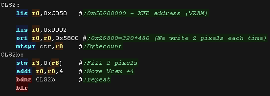 |
| The VRAM base is 0xC0500000, Each line of the screen is 640 pixels, and each pixel is 2 bytes. We multiply our X and Y pos to get the vram destination |
|
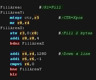
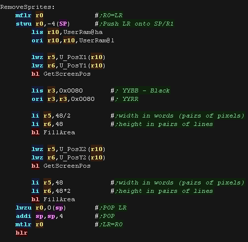
| The Fill Area routine removes a sprite from the
screen by drawing a clolor over the sprite This is used to remove the old sprites when they move |
  |
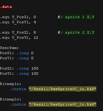
| We include the two bitmap files we want to draw as binary files. We also define memory to store the X and Y positions of the sprites. We also define 'offsets' so we can load and save the positions |
 |
| DrawSprites will redraw both the sprites onto the screen. We have a 'GetScreenPos' routine to convert an X,Y co-ordinate into a VRAM destination We use DrawBitmap1x to draw the small bitmap, Due to the way the GameCube shares colors between pixels there will be some color distortion. We use DrawBitmap2x to draw the doublesize version, This version uses 2x2 scaled pixels, so each 'pixel' will have its own unique color. |
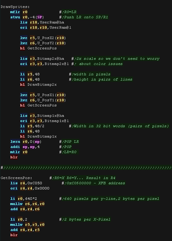 |
| We have 2 draw routines, though both are virtually identical. We store the Width in the CTR register. We read 2 pixels (32 bits) from the source (R3) and draw them to the screen (R8) The 2x source file has each pixel doubled horizontally in the file, but to double vertically we draw the same data one line down (offset 1280) |
|
Reading the joypad
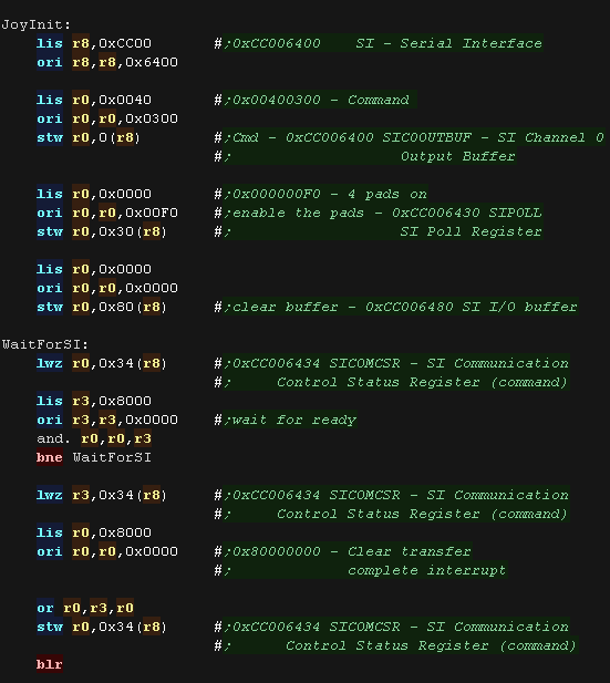
| We need to init the Serial Interface SI There's a sequence of commands we have to send to the hardware to prep the SI to send updates of the joypad and joysick. We have to set the 'Command' (0x00400300) using reg 0xCC006400 We enable all 4 pads by writing 0x000000F0 to 0xCC006430 We need to wati for the hardware to be ready - the top bit of 0xCC006434 will change to 0 once it is, we start the interrupt by writing 1 to the same bit of 0xCC006434 |
 |
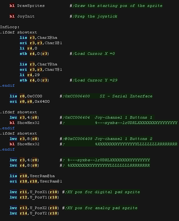
| We preo the joystick and start the main loop. At the start We read in the joysick buttons and analog directions into R3 and R4 We load the position of the two sprites X,Y into R11,R12 and R13,R14 |
 |
| We use R6 to test each bit of the digital joypad. We check each direction, it it's pressed we check the position of the sprite, we can't move if we're at the edge of the screen. If we CAN move, we add or subtract from that axis. We update R15, changing it to 1 - this is a flag to mark |
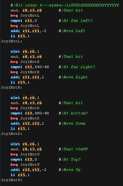 |
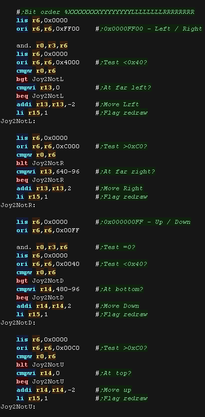
| We use R6 to test each direction of the digital
joypad. We mask the direction using 0xFF00 or 0x00FF We consider >0xC0 to be a move in one direction and <0x40 to be the opposite direction. We check each direction, it it's pressed we check the position of the sprite, we can't move if we're at the edge of the screen. If we CAN move, we add or subtract from that axis. We update R15, changing it to 1 - this is a flag to mark |
 |
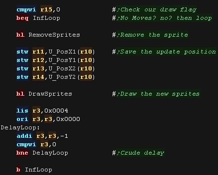
| We've checked all the moves. We now test R15 - if its zero no sprites have moved, so we jump back and check again. If a sprite has moved, we remove the old sprites, update the positions and redrawing the sprites. |
 |