

| The PowerPC processor is IBM's
Desktop CPU comparable to the Intel x86 CPUs. Based on the
previous POWER workstation CPUs, its RISC instruction set gave
impressive speed and capabilities. PowerPC became extremely popular around 2000, and was the basis for the Power Mac series, Gamecube, WII, Xbox360 and (to some extent) the PS3 |
 |
 |
If you want to learn POWERPC get the Cheatsheet! it has all the PowerPC commands, It will help you get started with ASM programming, and let you quickly look up commands when you get confused! |  |
 |
We'll
be
using GNU-EABI as our assembler for these tutorials You can get the source and documentation for GNU-EABI from the official website HERE |

Useful Documents
Because IBM hate us and want us to suffer, the official documents refer
to the leftmost bit of a 32 bit value as bit 0 - on any other CPU it
would usually be considered bit 31. We'll show
both conventions - in diagrams 'IBM bits' will refer to MSB=0...
'bits' will refer to the more common MSB=31
| IBM Documentation written by drunk madmen Bit 31 is Least significant rightmost bit Bit 0 is Most significant leftmost bit |
IBM Bit: 0.1.2.........29.30.31 MSB --------- LSB |
| Everyone else in the entire world ever Bit 0 is Least significant rightmost bit Bit 31 is Most significant leftmost bit |
Bit: 31.30.29.........2.1.0 MSB --------- LSB |
| Most Significant Bts | Least Significant Bits | |||||||||||||||||||||||||||||||
| Normal bit |
31 | 30 | 29 | 28 | 27 | 26 | 25 | 24 | 23 | 22 | 21 | 20 | 19 | 18 | 17 | 16 | 15 | 14 | 13 | 12 | 11 | 10 | 9 | 8 | 7 | 6 | 5 | 4 | 3 | 2 | 1 | 0 |
| IBM Bit |
0 | 1 | 2 | 3 | 4 | 5 | 6 | 7 | 8 | 9 | 10 | 11 | 12 | 13 | 14 | 15 | 16 | 17 | 18 | 19 | 20 | 21 | 22 | 23 | 24 | 25 | 26 | 27 | 28 | 29 | 30 | 31 |
| Bit Value | ... | ... | ... | ... | ... | ... | ... | ... | ... | ... | ... | ... | ... | ... | ... | ... | ... | ... | ... | ... | ... | ... | 512 | 256 | 128 | 64 | 32 | 16 | 8 | 4 | 2 | 1 |
| The PowerPC is
typically a BIG Endian system, certainly in the case of the
GameCube/WII, and apparently the Xbox 360 Though in fact the PowerPC can function in Little Endian mode |
 |
General Purpose Registers:
|
Floating Point Registers:
|
Special
Registers:
Note: There is no accessible PC register The value in NonVolatile registers must be preserved by subs R3-R10 are suggested for passing arguments to a sub RTOC (Table of contents) is suggested as a pointer to a table of addresses to variables for a subroutine, but this is optional! you can use it as a general register. R0 cannot be always be used like other registers Don't use R0 as a general maths register - Some commands (like ADDI) treat R0 like a hardwired zero R0 is used as a temp register during the 'Prolog/Epilog' of a sub (the Init and Cleanup of the stack during a sub. Use MFSPR or MTSPR for access to special register values |
Condition Register
The 32 bit condition register is split into 8x 4 bit parts.
| IBM Bits |
0-3 |
4-7 |
8-11 |
12-15 |
16-19 |
20-23
|
24-27
|
28-31
|
| Purpose |
CR0 |
CR1 |
CR2 |
CR3 |
CR4 |
CR5 |
CR6 | CR7 |
| Bits |
31-28
|
27-24
|
23-20
|
19-16
|
15-12
|
11-8 |
7-4 |
3-0 |
CR2, CR3 and CR4, are Non Volatile, and must be preserved by subs
Each of the 4 CR bits for CR0-CR7 have the following purpose:
| IBM Bit |
0 |
1 |
2 |
3 |
| Meaning (CMP Meaning) |
Negative (LT/FL) |
Positive (GT/FG) |
Zero (EQ/FE) |
Summary Overflow (SO/FU) |
| Bits |
3 |
2 |
1 |
0 |
FL/FG/FE and FO (Float Unordered) are used for floating point operations.
XER Register
use MFXER and MTXER to get or set the XER
| IBM Bit |
0 | 1 | 2 | 3-15 | 16-23 | 24
|
25-31 |
| Meaning |
SO |
OV |
CA |
0 0 0 0 0 0 0 0 0 0 0 0 0 |
Byte compare value |
0 | ByteCount |
| Bits | 31 |
30 |
29 |
28-16 | 15-8 | 7 | 6-0 |
CA - Carry
OV - Overflow
SO - Summary Overflow (Overflow that doesn't clear automatically)
Byte Count - used by lswx or stswx
BC BO,BI
BI= BIt of CR to use for condition
BO = Branch Operand as chart below
| BO Bits |
Meaning |
| 0000y | Decrement the CTR, then branch if the decremented CTR ? 0 and the condition is FALSE. |
| 0001y | Decrement the CTR, then branch if the decremented CTR = 0 and the condition is FALSE. |
| 0010y | Branch if the condition is FALSE. |
| 0100y | Decrement the CTR, then branch if the decremented CTR ? 0 and the condition is TRUE. |
| 0101y | Decrement the CTR, then branch if the decremented CTR = 0 and the condition is TRUE. |
| 0110y | Branch if the condition is TRUE. |
| 1000y | Decrement the CTR, then branch if the decremented CTR ? 0. |
| 1001y | Decrement the CTR, then branch if the decremented CTR = 0. |
| 10100 | Branch always. |
y= Likely True or False? (For branch prediction) / Branch Always has no Y bit
Addressing Modes
| Mode | Suffix | Format | Notes | Example |
| Signed Immediate | SIMM | 16 bit signed Immediate | addi rD,rA,SIMM |
|
| Unsigned Immediate | UIMM | 16 bit unsigned Immediate | ori rA,rS,UIMM |
|
| Register | rD,rA,rB | Leftmost param is destination (rD) | add rD,rA,rB |
|
| Register Indirect with immediate offset | d(rA) | Effective Address= value in rA + 16 bit signed immediate d | stb rS,d(rA) |
|
| Register Indirect with index | x | rA,rB | Effective Address = value in rA + rB U suffix will set rA=rA+rB |
lbzx rD,rA,rB |
| Register Indirect | Effective Address= value in rA | ? | ||
| Branch to Unconditional Address | imm_addr | 24 bit signed address | b imm_addr | |
| Branch to Conditional Address | target_addr | 14 bit signed address | blt target bc 12,O,target |
|
| Branch to register |
LR / CTR register contains address |
btlr eq |
Branch Psuedo ops
| BEQ | Branch if Equal |
| BGE | Branch if Greater or equal |
| BGT | Branch if Greater Than |
| BLE | Branch if Less or Equal |
| BLT | Branch if Less Than |
| BNE | Branch if Not Equal |
Loading a 32 bit address
Our immediates can only be 16 bit, so we need to use LIS (Load Immediate Shifted <<16) and ORI
We can get the High and low 16 bit halves of an address with @h and @l... but we need to have a signed value to add to an existing low part for LIS, which is provided by @ha (High sign-adjusted for Addition) ... so to load our 32 bit label 'InfLoop' we use:
lis r3,InfLoop@ha
addi r3,r3,InfLoop@l
Alternatively we can use @h with ORI for the same result
lis r3,InfLoop@h
ori r3,r3,InfLoop@l
Chars after a command
There are a few common suffixes to commands which enable options - of course, Not all suffixes are available to all commands!
. = Update Condition codes
z / ze = Zero extend
z = Add to zero (R0 acts as zero with some commands)
m = Minus one
a= algebraic (usually known as arithmetic Sign extended)
i = Immediate value
s = Shifted 16 bits (top half of 32 bit value = 0xFFFF---- )
w= Word (32 bits)
h= Half (16 bits)
b = Byte (8 bits)
c (Maths) = Carry - update CA of XER
c (Logical Ops) = Compliment - Bit flip
e = Extend - add Carry and update Carry (CA of XER)
o = Overflow (use Overflow bit of XER)
u = Update (Postincrement register)
x = indeXed (use second register as address offset rather than immediate
displacement)
+ = Branch prediction (Feeling positive - probably branch will occur!)
- = Branch prediction (Feeling Negative - Probably no branch!)
A template program
| To allow us to get started programming quickly and see the
results, we'll be using a 'template program'... This consists of 3 parts: A Header - this includes the hardware initialization to get things in a usable state. The Program - this is the body of our program where we do our work. A Generic Footer - this includes core graphics routines, and our 'monitor' debugging tools |
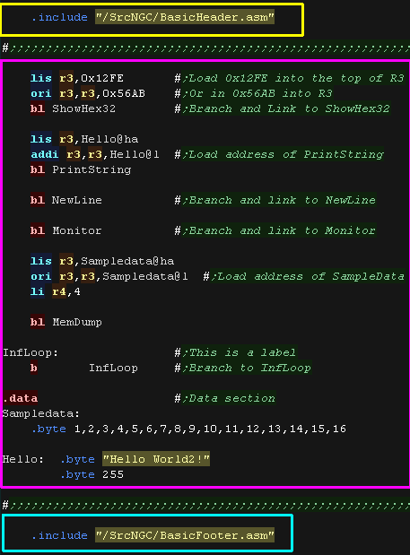 |
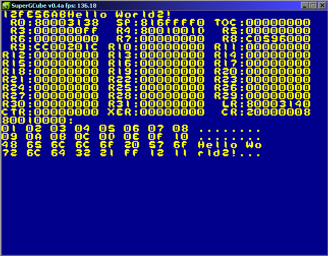
| The test program will dump a register to the screen, It will show a text string. It will then dump all the system registers. Finally it will show a memory area to the screen. These tools are designed for testing and debugging the PowerPC - we'll use them in our tutorials! |
 |
| The DevTools on this
website come with headers to allow this program to compile for the
gamecube, but without them you couldn't compile this program. It takes a lot more code to get either of these machines to even turn on the screen! |
|
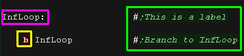
Commands, Labels and jumps
| Lets take a look at a simple program!... There will be times we need to jump around the code... the simplest way to do this is the command 'B'... this will Branch (like Jump or Goto) to another position in the code ... notice, commands like this are indented by a tab. Notice the line which is not indented and ends with a colon : - that makes it a label called 'InfLoop' ... labels tell the assembler to 'name' this position in the program - the assembler will convert the label to a byte number in the executable... thanks to the assembler we don't need to worry what number that ends up being... you'll also notice text in green starting with a Hash # - this is a comment (REMark) - they have no effect on the code (the ; is just to make Notepad++ color the comment nicely) |
 |
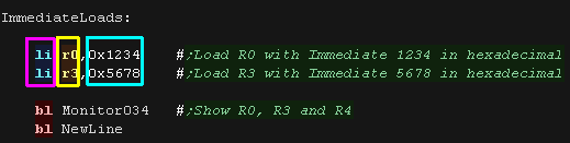
Loading values into registers
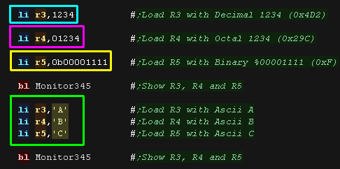
| We can load values into a register with the
LI command (Load Immediate) The destination register is on the left of the comma, the source (an immediate Hex value) is on the right. Our immediate starts with 0x (Zero X) this defines it as hexadecimal, not just regular decimal |
 |
| Here are the results, R0 and R3 were loaded with our test values |
 |
| A number on it's own will be Decimal A number starting 0 (Zero) will be Octal A number starting 0b (Zero B) will be Binary A character in quotes will be ASCII |
 |
| Here are the results | 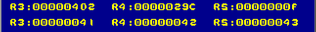 |
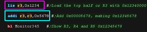
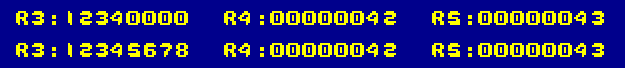
| Because an assembled command is 32 bit, we cannot load a full 32
bit value into the register in one go. What we can do is use LIS (Load Immediate Shifted to the top 16 bit) to set the top half, then ADDI to add the bottom 16 bit |
 |
 |
| Some of these commands are
'Psuedo-ops'... this is where the assembler compiles one command
into multiple in the final binary... It makes things easier for us to let the assembler to do as much of the work as possible, so we won't generally differentiate between Psuedo and 'Real' commands. |
 |
 |
WARNING! R1/SP is the stack pointer R2 is officially the TOC pointer (Table of contents) - a pointer to a var list for subs R3-R31 are general purpose registers on a 32 bit system, so use them for most of your work! |
| We can define a symbol with an EQUivalent value using EQU
- for example "TestVal,0xFEDCBA98" will define TestVal as
containing the value 0xFEDCBA98 We can then use TestVal in our code, and the assembler will replace this with the actual value. If we want to load a register with the 32 bit symbol value we need to split TestVal into two parts The assembler can calculate the two parts with the @HA and @L suffix... @HA gets the part to use with LIS @H would get the high part, but this wouldn't give the right signed value for ADDI... @HA get the High part for signed Addition. We can however use @H if we're using ORI to combine the High and Low parts |
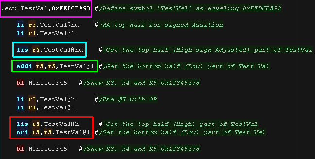 |
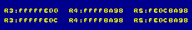
| In both cases R5 has been loaded with the value. |
 |
Moving Values, Adding and Subtraction
| We can copy a value from one register to another with the MR command (Move Register) The original value is unchanged Like before, the source (this time a register) is on the right, the destination register is on the left |
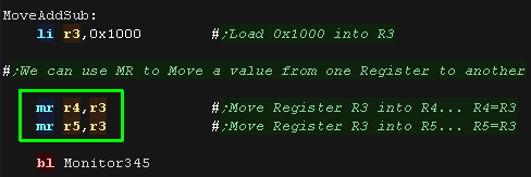 |
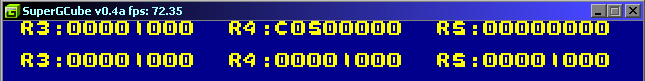
| Here are the results, we copied R3 to R4 and R5 |
 |
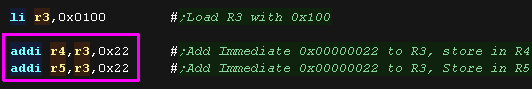
| If we want to add an immediate value we can use ADDI This takes 3 parameters, the leftmost parameter is the destination, the two on the right (the register and immediate) are the sources. |
 |
| Here are the results |
 |
| Here we're trying to perform "addi r0,r0,0x22"... but it won't work as expected! | 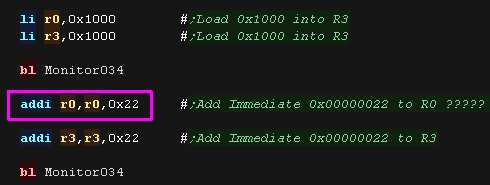 |
| Why does R0 equal 0x22, not 0x1022 ? Well R0 acts as the value Zero with the ADDI command! In fact the LI command we used before was actually a psuedo operation converted by the assembler into an "ADDI,R0,???" command! |
 |
| R0 only acts as
a hardwired zero with a few commands... you would need to check
the documentation (or cheatsheet)
to see which. But as a rule it's best not to use R0, just use R3+, and pretend R0-R2 don't exist! |
|
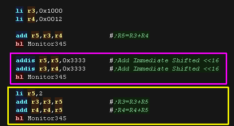
| Like LIS, there is an ADDIS which
adds a shifted value (shifted to the top half) A register can also be the source and destination of an add command - here we add R5 to R3 and R4 |
 |
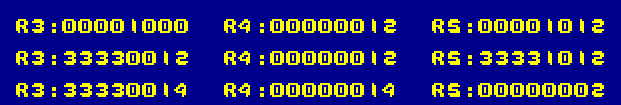
| Here are the results |
 |
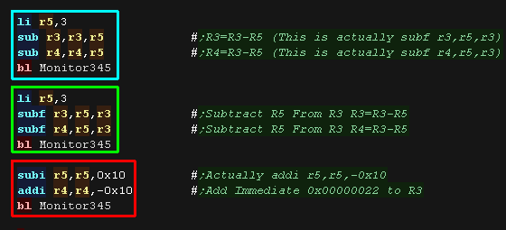
| We don't just need to add!... we can use SUB
to subtract! SUB will subtract the third parameter from the second parameter. Actually SUB is a psuedo-op which uses SUBF, which SUBtracts the second parameter From the third parameter (Subtract From) We also have an SUBI for immediate values - though actually this is a psuedo op for ADDI with a negative value |
 |
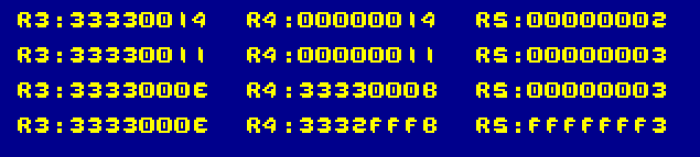
| Here are the results |
 |
Branches (Jumps), Branch & Link (Call to subroutine)
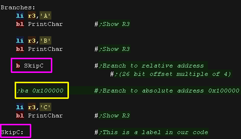
| Branches are like GOTO in basic. We can use B to branch to a label to skip over part of our code. Here we branch to the label SkipC We probably won't need it, but you can use BA to branch to an absolute address |
 |
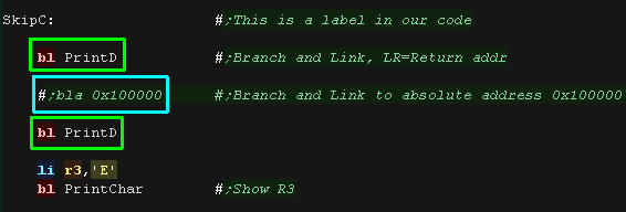
| We can call a subroutine with BL -
Branch an Link (like GOSUB in basic). This puts the return address
in the special LR register. we can call an absolute address with BLA |
 |
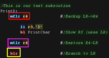
| Here's our subroutine. We use BLR to
Branch to Link Register (like RETURN in basic) But there's a problem!... if we call Printchar in the subroutine, the return address in LR will be lost... To avoid this we Move From the Link Register (MFLR) to R4 to back it up, then Move To the Link Register (MTLR) from R4 to restore it. |
 |
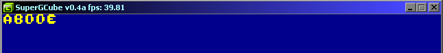
| Here's the result |
 |
| Lesson
2 - Addressing Modes and Stack Ok, we've looked at the basics, lets learn about the ways we can read and write data to memory, and how we can use the stack. |
 |
 Lesson2.asm |
 |
Addressing Modes
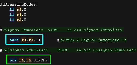
| Signed Immediate (SIMM) Many commands which take an immediate value take a 16 bit signed Immediate. The immediate is sign extended before use. Unsigned Immediate (UIMM) Some commands, like Logical operations, use a 16 bit unsigned Immediate. The immediate is zero extended before use. |
 |
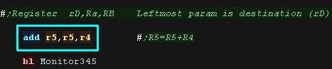
| Register addressing (rD) This is the simplest mode it refers to the use of a register as the source or destination parameter. |
 |
| Here is the results. |  |
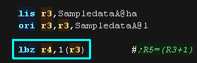
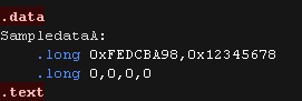
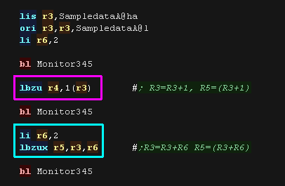
| Register Indirect with immediate offset (d(rA)) This uses a base register (in brackets) and an signed immediate offset (before the brackets) In this example 1(r3) we load a zero extended byte (LBZ - Load Byte and Zero extend) from the address in register R3, plus 1 We need some test data for the next mode. |
  |
| Here are the results |
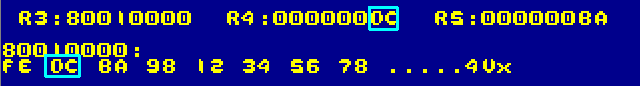 |
| Register Indirect with index (X Ra,Rb) Many commands support a register index (rather than an immediate). we add an X suffix to the command, and specify two registers which are added together and used as the source address, The first is the Base register, the second is the Offset register |
 |
| Here are the results |
 |
| With Update (U) We can add an U suffix to update the base register, the offset is added to the base register before the command occurs - this could be called PreIncrement on other systems We can combine U and X to use a register as an offset |
 |
| Here are the results |
 |
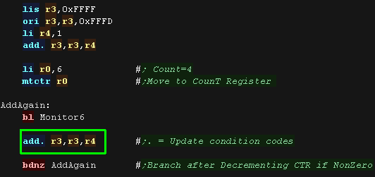
| With CR Update (.) We can add a . suffix (full stop) to update the Condition Register (flags) Here we repeatedly add 1 to R3, and show the CR each time. Note: Don't wory about MTCTR and BDNZ - these are a loop, but we'll look at them later. |
 |
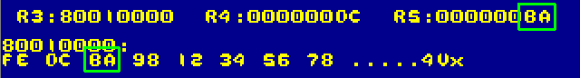
| Here are the results, when R3 overflows to zero, the CR register changes to reflect the results. | 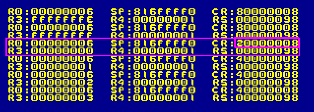 |
| Many commands support
these kind of suffixes, but not all! Check out the cheatsheet for details of what's available. |
|
Load and Store
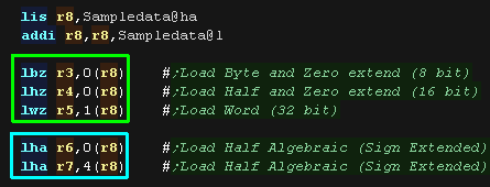
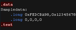
| When loading data from memory, we can Load an 8 bit Byte, a 16 bit
Half or 32 bit Word. LBZ,LHZ and LWZ will fill any unloaded bits with Zero, intended for unsigned numbers. If we want to load a signed 16 bit half we can use LHA (Load Half Algebraic) which will sign extend the read data. As LWZ loads the full register it works fine for signed numbers, there is no command for loading signed bytes, but you can load a byte with LBZ, then sign extend with EXTSB |
  |
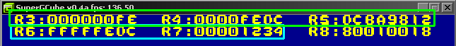
| Here are the results |
 |
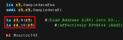
| If we want to know the final address used by the commands
(Effective Address) we can use LA -
Load Address LA will store the effective address in a register |
 |
| Here are the results |
 |
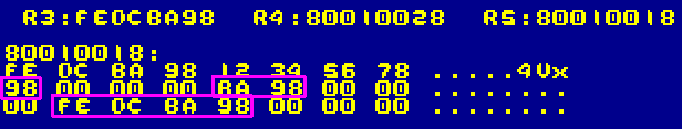
| As well as loadin, we can Store! STB, STH and STW will store an 8 bit Byte, a 16 bit Half or 32 bit Word. These will work for signed or unsigned numbers. |
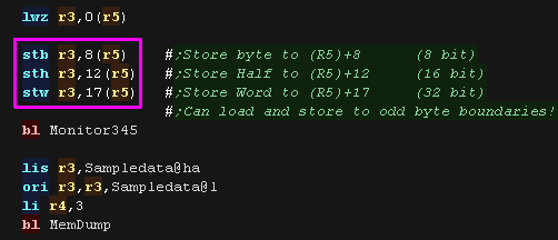 |
| Here are the results |
 |
|
Typically the PowerPC is a BIG ENDIAN
machine, meaning it stores the most significant byte of a 32 bit
word first in memory. But this is actually optional, the CPU can be set to run in LITTLE ENIAN mode, where the least significant byte is stored first! |
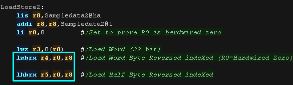
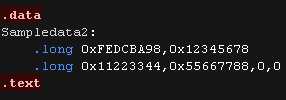
| If we want to load data in reverse order (Little endian on a big
endian machine) we can use LWBRX (32 bit) or
LHBRX (16 bit) There are matching store commands too. |
  |
| Here is the results |
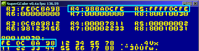 |
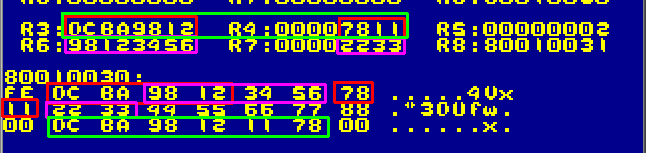
| The PowerPC has what it calls 'String commands' These will load or store a sequence of bytes to one or more consecutive registers. LSWI will use an immediate byte count LSWX will use the count in the bottom 7 bits of the special XER register STSWI will store a sequence of bytes from an immediate byte count STSWX will use the count in the bottom 7 bits of the special XER register |
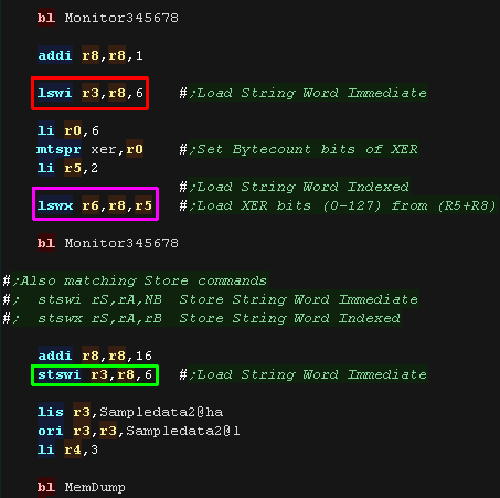 |
| Here are the results. When we load counts that are not multiples of 8, the address the bytes are loaded from may not be as we expect |
 |
The Stack!
| The Stack is a temporary store, we use SP (the same register as
R1) to track our stack pointer. It moves down in memory towards zero
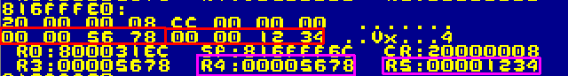
as items are 'Pushed' onto the stack To back up an item (Push), we use Update mode and a command like "stwu r3,-4(SP)" to decrease the stack pointer and put an item onto the stack Restoring an item (Pop) requires two commands, we use command like "lwzu r5,0(sp) addi sp,sp,4" to restore the item and update the stack pointer. |
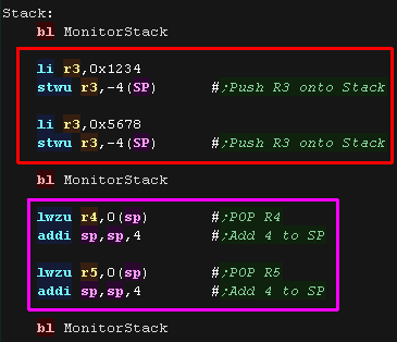 |
| Here are the results Notice we pushed R3 twice, but popped into R4 and R5 |
 |
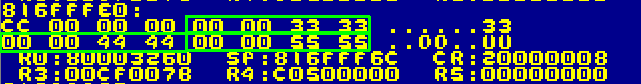
| We will often want to back up many, or all of our registers in one
go We can do this with STMW (Store Multiple Words) and LMW (Load Multiple Words) We specify a starting register (shown here as R29), all the higher register numbers will also be backed up (in this case R29,R30,R31) |
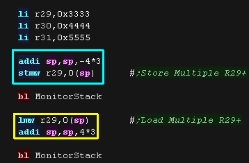 |
| Here we backed up 3 registers onto
the stack |
 |
| There are some special registers we may want to back up that we
can't use directly, Namely the Link Register (LR) and the Condition register (CR) We can back these up indirectly via R0 - In fact this is pretty much what R0 is for! Here we back up R0, the Condition Register and Link Register. We run our test then restore LR,CR and R0 |
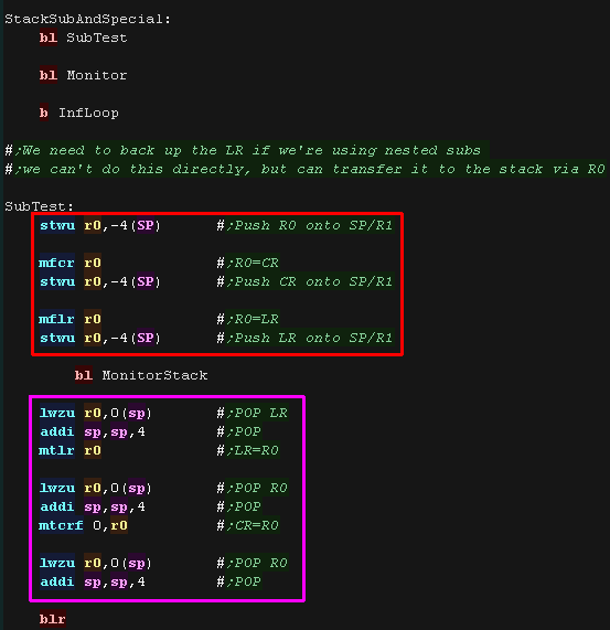 |
| Our three registers were backed up and restored via the stack. Note the LR doesn't quite match - as it was changed by the "BL Monitor" command. |
 |
 |
For the Compare examples you'll want to make sure you download the code, and try changing the test values so you understand what the conditions actually do. |
Compares
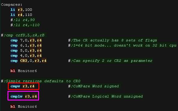
| The PowerPC CMP command is rather over complex!... the
Condition Register actually has 8 sets of flags we can select, and
supports a 'Long' (64 bit mode) Generally though, we can avoid using this mode, and just use CMPW (for signed numbers) and CMPLW (for unsigned numbers) |
 |
||||||||||||||||||||
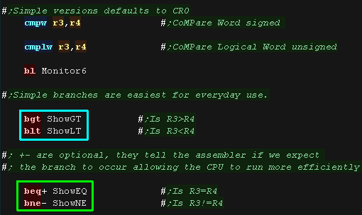
| We can use simple branch commands like BGT
and BLT to branch based on the flags set by CMPW and
CMPLW We don't have to, but we can add a + or - to these commands to tell the cpu if we expect the branch to occur (+) or not occur (-). This tells the CPU how to most efficiently process the commands, as it knows whether the command following the branch is likely to execute, or if the processor pipeline is likely to need flushing. |
 |
||||||||||||||||||||
| In the example R3 (100) was less than R4 (110) - so the BLT branch occurred | 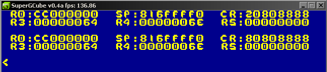 |
||||||||||||||||||||
| Here is a full list of the available branch 'Bcc type' commands: | blt target Branch if less than ble target Branch if less than or equal beq target Branch if equal bge target Branch if greater than or equal bgt target Branch if greater than bnl target Branch if not less than bne target Branch if not equal bng target Branch if not greater than bso target Branch if summary overflow bns target Branch if not summary overflow bun target Branch if unordered bnu target Branch if not unordered |
||||||||||||||||||||
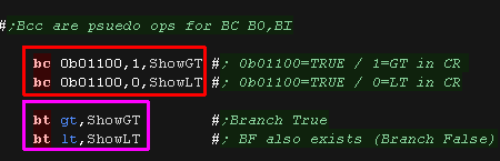
| Actually the Bcc type commands like BGT and BEQ are actually
Psuedo-ops They use the BC command, which takes a complex 5 bit condition (shown below),and a single bit number of the CR to compare. There are also BT (Branch True) and BF (Branch False) commands which use a two character condition. However there's no real need to use these. The Bcc codes are easier to use, and do all we need |
 |
||||||||||||||||||||
|
|||||||||||||||||||||
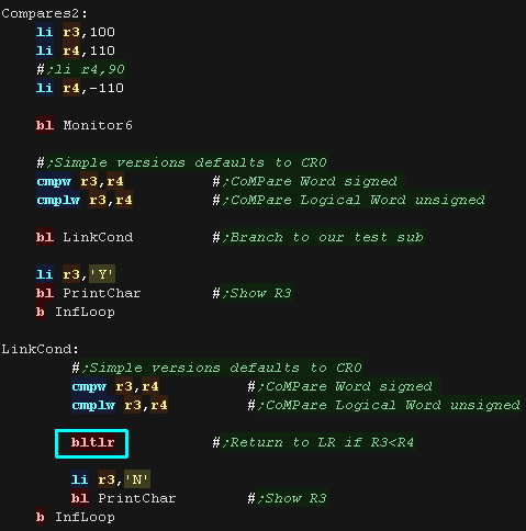
| We can actually branch to the link register based on a condition
(Kind of like RET Z on the Z80) Herer we use BLTLR to Branch if LessThan to the LinkRegister |
 |
||||||||||||||||||||
| Here are the results | 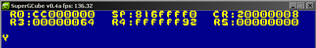 |
||||||||||||||||||||
The Condition Register
| There will be times we need to work with the Condition Register
itself (CR) We can copy the CR to another register with MFCR We can transfer back from a register to the CR with MTCRF - this takes a byte 'bitmask' with each of the 8 bits in the mask defining if that CR Field is transferred (IBM Bit order - Bit 0 = Top bit)... 0xFF will transfer to ALL the CR Fields. |
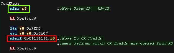 |
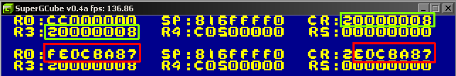
| We copied CR to R3. We then copied 7 of the fields from R0 to the CR |
 |
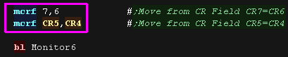
| We can transfer between fields inb the CR using MCRF
(Move Condition Register Field) These can be specified as a simple number 0-7 or CR0-CR7 The destination is on the left of the comma, the source is on the right. |
 |
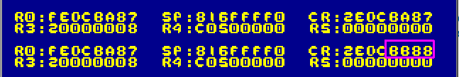
| Here are the results |
 |
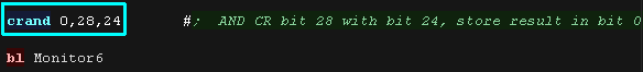
| It's not clear why we would want them, but there is a wide range
of bit operation commands. Here we use CRAND to AND condition register bit 28 with bit 24, and store result in bit 0 |
 |
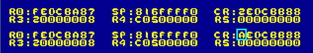
| Here are the results. |
 |
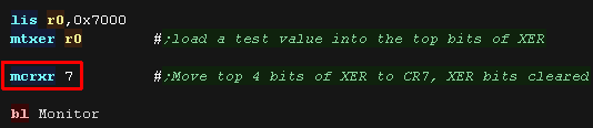
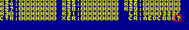
| If we need to, we can gain access to the flags in the XER by
transferring them to a CR Field with MCRXR (Move
To Condition Register from XeR) This also clears the top 4 XER bits |
 |
| Here are the results |
 |
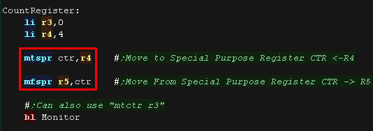
The Count Register for loops
| We could use CMP commands and BNE to effect a loop, however the
Power PC has a special register called the CounT Register (CTR) This can't be accessed directly, but we can use MTSPR and MFSPR to access it's value. MTCTR is also a psuedo-op for "MTSPR CTR,???" Here we use MTSPR to set the Count to 4 |
 |
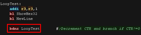
| Once we've set the CTR, we can use BDNZ (Branch
after Decrement if ctr NonZero) This allows us to decrement, compare and loop in a single command. |
 |
| Here are the results |
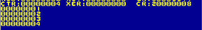 |
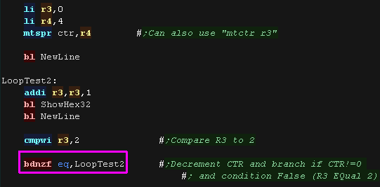
| We can combine two conditions in the branch - Here we use BDNZF, this will repeat provided the
decremented CTR is NonZero, and the condition (EQual) is False. |
 |
| Here are the results |  |
 |
There
is a crazy number of permutations of condition and flag masking
commands. We're only looking at the essentials!... Please see the cheatsheet or official docs for the full range |
| Lesson
4 - Logical Ops, Signs and Shifts Lets continue by learning some of the slightly more obscure mathematical operations |
|
Lesson4.asm |
|
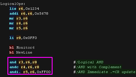
| Logical operations perform a comparison one bit at a time. The parameter on the left is the destination, the second parameter is the source (R6 in the example), the third is the mask to be applied (R0 or an immediate in the example). Where a bit in both parameters are 1, after the AND operation the result in rA will be 1, when they are not it will be 0. Here we used AND, AND C (And Complement - All the bits in the mask parameter are flipped before the AND operation) and ANDI. (And Immediate with CR Update |
 |
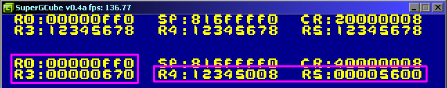
| Here are the results. AND can be thought of as clearing bits in the destination to zero. |
 |
| OR will also compare the source and mask. where a bit in either
parameters are 1 the result in rA will be 1, when they are not it
will be 0. Here we used OR, ORC (Or Compliment - All mask bits flipped) and ORIS (Or Immediate shifted to the top 16 bits) |
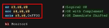 |
| Here are the results. OR can be thought as setting the bits in the destination to 1 |
 |
| XOR is a bit flipping operation (Inversion). Where a bit in the
second mask parameter is 1 the bit in the source is flipped and
stored in the destination, when it's 0, it's transferred unchanged. Here we used XOR, XORI (Xor Immediate) and XORIS (Xor Immediate Shifted to the top bits) |
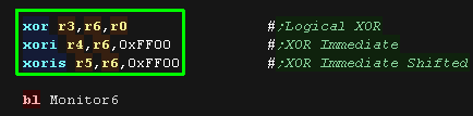 |
| Here are the results. The 1 bits in the mask were flipped in the destination |
 |
| Logical NAND is a bit odd!... it
performs an AND, then complements (bit flips) the result (NOT) Where a bit in either parameter is 0 the result will be 1, when they are both 1 it will be 0. A ones complement (bit flipped) version of a register can be calculated by using this command, where moth parameters are the same, for example "NAND R3,R4,R4" will set R3 to the complement of R4. |
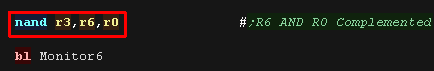 |
| Here are the results |
 |
| EQV stands for EquiValent... it
performs XOR followed bt a complement (Bit flip) This XOR-Complement is sometimes called XNOR (eXclusive NOR). |
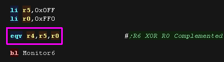 |
| Logical XNOR (EQV) will return 1 when the contents of both parameters are the same, returning 0 if they are different, effectively returning 1 (true) if they the bits are equivalent. |  |
| There are two other commands we'll cover here NOT flips all the bits (Complement) NEG converts a positive to a negative, it's the equivalent of flipping the bits and adding one. |
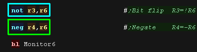 |
| Here are the results |  |
| The available options for the
mask commands are alittle unpredictable! There is an ANDI. but no ORI. (only ORI) there's an ORC but no XORC! Check the Cheatsheet to see what's available |
|
Signs and Zeros
| There may be times we have a
signed 8 bit byte or 16 bit half that we need to sign extend to fill
the 32 bit register We can use EXTSB to extend a signed byte, or EXTSH to extend a half This effectively fills all extra bits with the original top bit. |
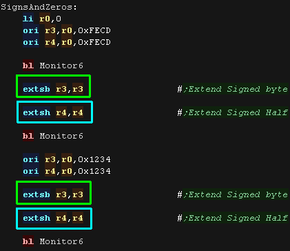 |
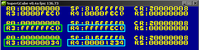
| Here are the results |
 |
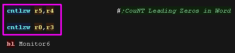
| If for some reason you need to know how many zeros there are on
the left of your register you can use CNTLZW This will CouNT the Leading Zeros in the Word |
 |
| Here are the results |
 |
Bit Shifts
| There will be times we want
to shift bits in a register... One good reason is multiplication!
When we shift the bits left, we effectively double a number. SLW will shift the bits in a parameter left - the third parameter is the number of bits to shift. SLW. will also update the CR flags. This command works fine for signed or unsigned numbers. |
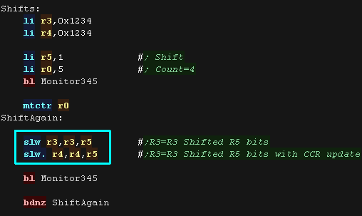 |
| Here are the results |
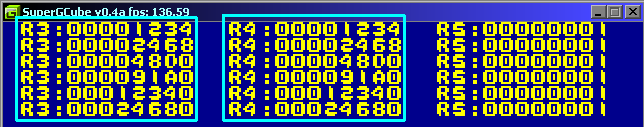 |
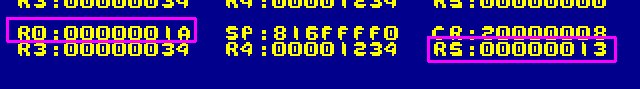
| We can shift right to halve a number. SRW will shift a word right - it's designed for unsigned numbers - new top bits will be zero SRAW/SRAWI will shift a word right for Algebra (Ari thematic) - it's designed for signed numbers, as new bits preserve the old top bit |
 |
| Here are the results of shifting signed and unsigned numbers. |
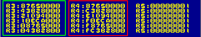 |
| There may be times we only want a few bits from a parameter - like
if we're reading directions from a joypad - and we may want to move
them too! Rotate Left Word then aNd Mask will rotate a parameter by a number of bits, then keep only a range of the consecutive bits copying them into the destination, the other bits are zeroed. The syntax is: RLWNM Dest,Src,BitShift,FirstBitToKeep,LastBitToKeep We can also use an immediate bit shift with RLWINM Remember: the bit range is in IBM Bit numbers, so bit 0 is the leftmost most significant bit, and bit 31 is the rightmost least significant bit. |
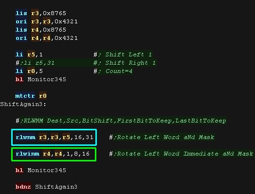 |
| Here are the results. |
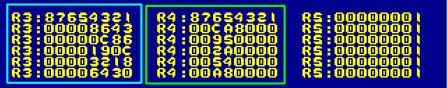 |
| Rather than just zeroing the other bits, we can actually insert
the shifted bits into an existing register with RLWIMI
- Rotate Left Word Immediate then Mask Insert. This will shift and mask the bits of the source, then insert them into the destination, leaving the other destination bits unchanged! The Syntax is: RLWIMI Dest,Src,BitShift,FirstBitToKeep,LastBitToKeep |
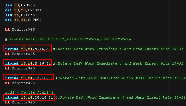 |
| Here are the results - the bottom 4 bits of R3 are altered by the
command. |
 |
| Lesson
5 - Maths and More! There's a few more maths commands we need to cover, and some weirder commands we'll finish by mentioning! |
|
Lesson5.asm |
|
Carrying for 64 bit maths
| Like most processors,we can use the Carry Flag to 'span'
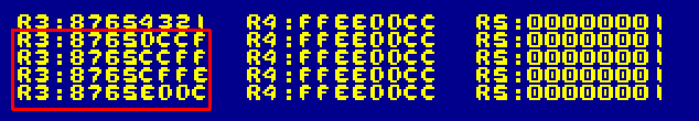
mathematical operations across two registers. On the PowerPC the CArry flag (CA) is in the top bits of the XER register We use ADDC or ADDIC to add the low part and update the XER[CA] flag (ADD Carry) For the high part we then use ADDE, or ADDZE if we just want to add the carry (ADD Extended / ADD to Zero Extended) |
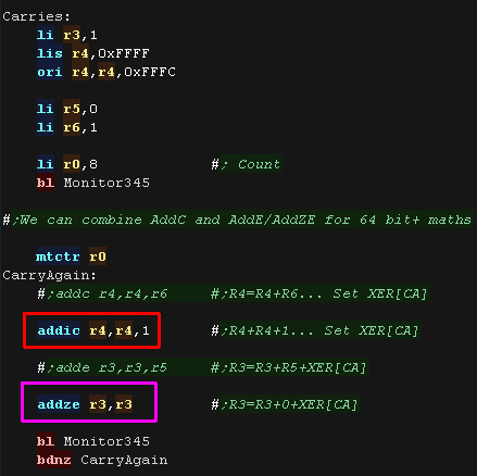 |
| The addition was spanned across two registers. |
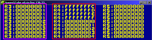 |
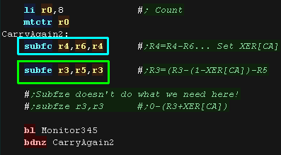
| We can do the same with SUBFC (Subtract
From with Carry) for the low part, We use SUBFE (Subtract From with Extend) for the high part , this subtracts the second parameter plus XER[CA] from the third parameter, storing the result in the destination register. Note, there is a SUBFZE, but it doesn't help us here! |
 |
| Here are the results. |
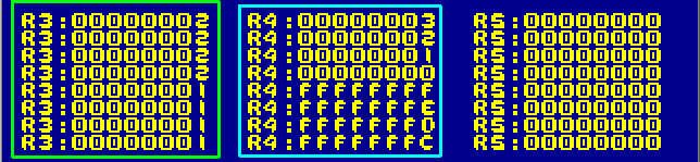 |
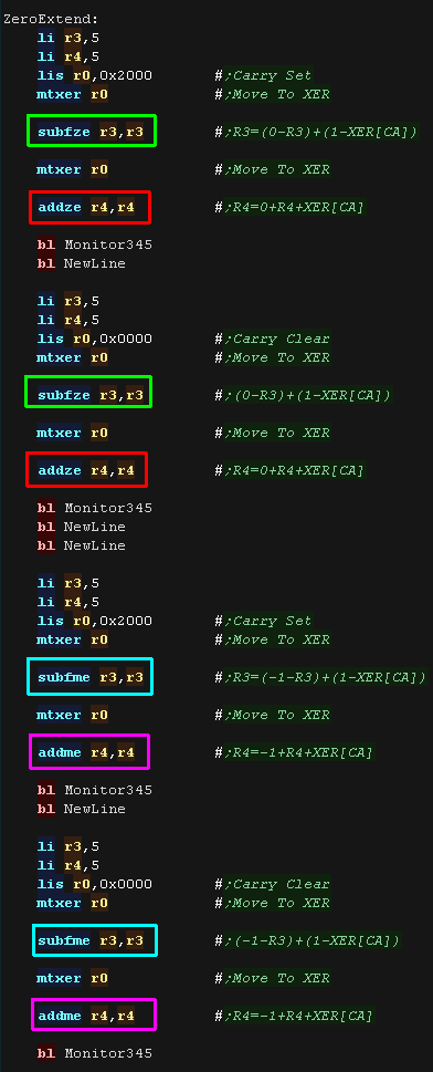
Zero and Minus one Extend
| We have commands
to add and subtract from 0 or -1 with the Carry flag acting as an
Extend bit ADDZE will ADD to Zero with Extend ADDME will ADD to Minus one with Extend SUBFZE will SUBtract From Zero with Extend SUBFME will SUBtract From Minus one with Extend |
 |
| Here are the results |
 |
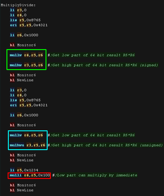
Multiplication and Division
| Multiplication on the Power
PC can work in 64 bit - That is we multiply two 32 bit numbers, and
get a 64 bit pair of registers as a result. Actually we need to use two commands to get the full 64 bits - we can use just one if we only want a 32 bit result. The pair of commands we need to use depend on if we are using signed numbers, or unsigned ones. For signed numbers we use MULLW for the low part, and MULHW for the high part. For unsigned numbers we use MULLW for the low part, and MULHWU for the high part. You'll notice we use MULLW for the low part in both cases... in fact there is an immediate version - MULLI for the low part too. (There's no high part immediate command) |
 |
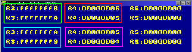
| Here are the results. |
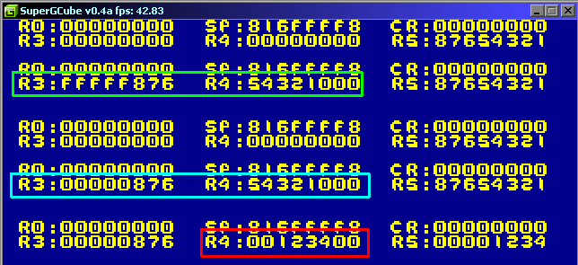 |
| We can also do division, however this is only 32 bit. DIVW will divide signed numbers DIVU will divide unsigned numbers |
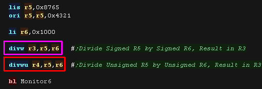 |
| Here are the results |
 |
Special commands
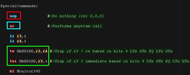
| You may not need them, and
they may even do nothing on your system, but there are some system
call command you may need. SC will perform a system call - What it does depends on the operating system. TW / TWI will perform a TRAP based on a condition comparing two registers, or a register and an immediate - if any of the conditions are true, the trap will occur. The Trap condition flags define what Signed/Unsigned conditions will apply in the format: % LTs GTs EQ LTu GTu Finally there's the NOP command - No-Operation - it does nothing but can be used as a delay or for self modifying code. |
 |
Instruction Set Summary
| Opcode | Integer Arithmetic Instructions | Details .=updateCR o=overflow c=carry e=extended m=minus one z=zero as param (R0) | R0=0? |
| addi rD,rA,SIMM | Add Immediate | The sum (rAID) + SIMM is placed into register rD. |
Y |
| addis rD,rA,SIMM | Add immediate shifted | The sum (rA| 0) + (SIMM || x'0000') is placed into rD. | Y |
| add rD,rA,rB | Add | The sum (rA) + (rB) is placed into register rD. add. rD,rA,rB addo rD,rA,rB addo. rD,rA,rB |
- |
| subf rD,rA,rB | Subtract from | The sum --. (rA) + (rB) + 1 is placed into rD subf. rD,rA,rB subfo rD,rA,rB subfo. rD,rA,rB |
- |
| addic rD,rA,SIMM | Add Immediate Carrying | The sum (rA) + SIMM is placed into register rD. addic. rD,rA,SIMM |
- |
| subflc rD,rA,SIMM | Subtract from Immediate Carrying | The sum --. (rA) + SIMM + 1 is placed into register rD. | - |
| addc rD,rA,rB | Add Carrying | The sum (rA) + (rB) is placed into register rD. addc. rD,rA,rB addco rD,rA,rB addco. rD,rA,rB |
- |
| subfc rD,rA,rB | Subtract from Carrying | The sum -, (rA) + (rB) + 1 is placed into register
rD. subfc. rD,rA,rB subfco rD,rA,rB subfco. rD,rA,rB |
- |
| adde rD,rA,rB | Add Extended | The sum (rA) + (rB) + XER(CA) is placed into
register rD. adde. rD,rA,rB addeo rD,rA,rB addeo. rD,rA,rB |
- |
| subfe rD,rA,rB | Subtract from Extended | The sum -,(rA) + (rB) + XER(CA) is placed into
register rD. subfe. rD,rA,rB subfeo rD,rA,rB subfeo. rD,rA,rB |
- |
| addme rD,rA | Add to Minus One Extended | The sum (rA) + XER(CA) + x'FFFFFFFF' is placed into
register rD. addme. rD,rA addmeo rD,rA addmeo. rD,rA |
- |
| subfme rD,rA | Subtract from Minus One Extended | The sum..., (rA) + XER(CA) + x'FFFFFFFF' is placed
into register rD. subfme. rD,rA subfmeo rD,rA subfmeo. rD,rA |
- |
| addze rD,rA | Add to Zero Extended | The sum (rA) + XER(CA) is placed into register rD addze. rD,rA addzeo rD,rA addzeo. rD,rA |
- |
| subfze rD,rA | Subtract from Zero Extended | The sum..., (rA) + XER(CA) is placed into register
rD. subfze. rD,rA subfzeo rD,rA subfzeo. rD,rA |
- |
| neg rD,rA | Negate | NEGate register rA, and store the results in
register rD. This converts a positive to a negative and vice
versa. neg. rD,rA nego rD,rA nego. rD,rA |
- |
| Opcode | Integer Compare Instructions | Details .=updateCCR o=Overflow | |
| mulli rD,rA,SIMM | Multiply Low Immediate | The low-order 32 bits of the 48-bit product (rA)*SIMM are placed into rD. Use with mulhw for full 64 bit | - |
| mullw rD,rA,rB | Multiply Low | The low-order 32 bits of the 64-bit product (rA)
*(rB) are placed into rD. Use with mulhwu for full 64 bit mullw. rD,rA,rB mullwo rD,rA,rB mullwo. rD,rA,rB |
- |
| mulhw rD,rA,rB | Multiply High Word | The contents of rA and rB are interpreted as 32-bit
signed integers.This gives the top 32 bit of the 64-bit product. mulhw. rD,rA,rB |
- |
| mulhwu rD,rA,rB | Multiply High Word Unsigned | The contents of rA and rB are interpreted as 32-bit
unsigned integers.This gives the top 32 bit of the 64-bit
product. mulhwu. rD,rA,rB |
- |
| divw rD,rA,rB | Divide Word | rD= rA (signed) / rB (signed). To Get Signed
Remainder: divw rD,rA,rB rD = quotient mull rD,rD,rB rD =
quotient*divisor subf rD,rD,rA rD = remainder divw. rD,rA,rB divwo rD,rA,rB divwo. rD,rA,rB |
- |
| divwu rD,rA,rB | Divide Word Unsigned | rD= rA (unsigned) / rB (unsigned). To Get Unsigned
Remainder: divwu rD,rA,r8 rD = quotient mull rD,rD,r8 rD =
quotient*divisor subf rD,rD,rA rD = remainder divwu. rD,rA,rB divwuo rD,rA,rB divwuo. rD,rA,rB |
- |
| Opcode | Integer Compare Instructions | Details i=immediate w=word | |
| cmp crfD,L,rA,rB | Compare (Signed) | CoMPare signed rA with signed rB, storing results
in CR field crfD. L=Length (32/64 bits) cmpi crfD,L,rA,SIMM cmpw crfD,rA,rB (cmp crfD,O,rA,rB) cmpwi crfD,rA,SIMM (cmpi crfD,O,rA,SIMM) |
- |
| cmpl crfD,L,rA,rB | Compare Logical (unsigned) | CoMPare unsigned rA with unsigned rB, storing
results in CR field crfD. L=Length (32/64 bits) cmpli crfD,L,rA,UIMM cmplwi crfD,rA,UIMM (cmpli crfD,O,rA,UIMM) cmplw crfD,rA,rB (cmpl crfD,O,rA,rB) |
- |
| Opcode | Integer Logical Instructions | Details .=updateCR i=immediate s=shifted c=complement / b=byte h=half | |
| and rA,rS,rB | AND | The contents of rS is ANDed with the contents of
register rB and the result is placed into rA. and. rA,rS,rB andi. rA,rS,UIMM andis. rA,rS,UIMM andc rA,rS,rB andc. rA,rS,rB |
- |
| or rA,rS,rB | OR | The contents of rS is ORed with the contents of rB
and the result is placed into rA. or. rA,rS,rB ori rA,rS,UIMM oris rA,rS,UIMM orc rA,rS,rB orc. rA,rS,rB |
- |
| xor rA,rS,rB | XOR | The contents of rS is XORed with the contents of rB
and the result is placed into register rA. xor. rA,rS,rB xori rA,rS,UIMM xoris rA,rS,UIM |
- |
| nand rA,rS,rB | NAND | The contents of rS is ANDed with the contents of rB
and the one's complement of the result is placed into register
rA. NAND with rA=rB can be used to obtain the one's complement. nand. rA,rS,rB |
- |
| nor rA,rS,rB | NOR | The contents of rS is ORed with the contents of rB
and the one's complement of the result is placed into register
rA. nor. rA,rS,rB |
- |
| eqv rA,rS,rB | Equivalent | The contents of rS is XORed with the contents of rB
and the complemented result is placed into register rA. eqv. rA,rS,rB |
- |
| extsb rA,rS extsh rA,rS |
Extend Sign Byte / Halfword | Register r S[24-31] are placed into rA[24-31]. Bit
24 of rS is placed into rA[O-23]. extsb. rA,rS extsh. rA,rS |
- |
| cntlzw rA,rS | Count Leading Zeros Word | Count of leading zero bits of rS is placed into rA.
This number ranges from 0 to 32, inclusive. cntlzw. rA,rS |
- |
| Opcode | Integer Rotate Instructions | Details .=updateCR | |
| rlwinm rA,rS,SH,MB,ME | Rotate Left Word Immediate then AND with Mask | Rotate rS left by SH bits, and keep (AND) bits
MB-ME, storing results in rA EG: rlwinm r3,r4,8,24,31 will shift R4<<8 and keep bits 24-31 (0=MSB 31=LSB) rlwinm. rA,rS,SH,MB,ME |
- |
| rlwnm rA,rS,rB,MB,ME | Rotate Left Word then AND with Mask | Rotate rS left by rB bits, and keep (AND) bits
MB-ME, storing results in rA EG: rlwinm r3,r4,8,24,31 will shift R4<<8 and keep bits 24-31 (0=MSB 31=LSB) rlwnm. rA,rS,rB,MB,ME |
- |
| rlwimi rA,rS,SH,MB,ME | Rotate Left Word Immediate then Mask Insert | Rotate rS left by SH bits, and transfer bits MB-ME
into rA (leaving other bits unchanged) EG: rlwinmi r3,r4,8,24,31 will shift R4<<8 and transfer bits 24-31 (0=MSB 31=LSB) to R3, bits 0-23 of R3 are unchanged rlwimi. rA,rS,SH,MB,ME |
- |
| Opcode | Integer Shift Instructions | Details .=updateCR | |
| slw rA,rS,rB | Shift Left Word | rS is shifted left rB bits. Bits shifted out are
lost. new bits on the right are 0. slw. rA,rS,rB |
- |
| srw rA,rS,rB | Shift Right Word (Unigned) | rS is shifted right rB bits. New bits on the left
are 0. srw. rA,rS,rB |
- |
| srawi rA,rS,SH | Shift Right Algebraic Word Immediate (Signed) | rS is right SH bits. Bits shifted out are lost. New
bits on the left retain the old top bit, keeping the sign.
XER[CA] is set if r S contains a negative number and any 1-bits
are shifted out of position 3, otherwise XER(CA) is cleared. srawi. rA,rS,SH |
- |
| sraw rA,rS,rB | Shift Right Algebraic Word (Signed) | rS is shifted right rB[26-31] bits. New bits on the
left retain the old top bit, keeping the sign. XER[CA] is set to
1 if rS contains a negative number and any 1-bits are shifted
out of position 31; otherwise XER[CA] is cleared to O. A If
rB[26]= 1, then rA is filled with 32 sign bits (bit 0) from rS.
Condition register field CRO is set based on the value written
into rA. sraw. rA,rS,rB |
- |
| Opcode | Integer Load Instructions | Details b=byte h=half w=word / z=zero extend (unsigned) a=algebraic (Sign extended) u=update x=indexed | |
| Ibz rD,d(rA) | Load Byte and Zero | Load and zero extend an 8 bit byte from the
effective address. lbzx rD,rA,rB lbzu rD,d(rA) lbzux rD,rA,rB |
Y |
| lhz rD,d(rA) | Load Half Word and Zero | Load and zero extend a 16 bit half word from the
effective address. lhzx rD,rA,rB lhzu rD,d(rA) lhzux rD,rA,rB |
Y |
| Iha rD,d(rA) | Load Half Word Algebraic | Load and sign extend an 16 bit half word from the
effective address. Ihax rD,rA,rB Ihau rD,d(rA) Ihaux rD,rA,rB |
Y |
| Iwz rD,d(rA) | Load Word and Zero | The effective address is the sum (rAI0)+d. The word
in memory addressed by the EA is loaded into register rD[0-31]. lwzx rD,rA,rB lwzu rD,d(rA) lwzux rD,rA,rB |
Y |
| Opcode | Integer Store Instructions | Details b=byte h=half w=word / x=indexed u=update | |
| stb rS,d(rA) | Store Byte | The effective address is the sum (rA|0) + d.
Register rS[24�31] is stored into the byte in memory addressed
by the EA. stbx rS,rA,rB stbu rS,d(rA) stbux rS,rA,rB |
Y |
| sth rS,d(rA) | Store Half word | The effective address is the sum (rAIO)+d.
rS[16-31] is stored into the half-word in memory addressed by
the EA. sthx rS,rA,rB sthu rS,d(rA) sthux rS,rA,rB |
Y |
| stw rS,d(rA) | Store Word | The effective address is the sum (rAIO)+d. Register
rS is stored into the word in memory addressed by the EA. stwx rS,rA,rB stwu rS,d(rA) stwux rS,rA,rB |
Y |
| PsuedoOps | Miscellaneous Simplified Mnemonics | Details | |
| no-op | No-Op | (equivalent to ori 0,0,0) | - |
| li rD,value | Load Immediate | Load a 16-bit signed immediate value into rA (equivalent to addi rA,0,value) | - |
| lis rD,value | Load Shifted Immediate | Load a 16-bit signed immediate value, shifted left by 16 bits, into rA (equivalent to addis rA,0,value) | - |
| la rD,SIMM(rA) | Load Address | equivalent to addi rD,rA,SIMM | - |
| la rD,v | Load Address | Load Effective addres of Base+Offset (equivalent to addi rD,rA,SIMM) | - |
| mr rA,rS | Move Register | (equivalent to or rA,rS,rS) | - |
| not rA,rS | Complement Register | (equivalent to nor rA,rS,rS) | - |
| sub rD,rA,rB | Equivalent to subf rD,rB,rA | - | |
| subi rD,rA,SIMM | Equivalent to addi rD,rA,-SIMM | - | |
| Opcode | Integer Load and Store with Byte Reversal Instructions | Details | |
| lhbrx rD,rA,rB | Load Half Word Byte-Reverse Indexed | Load unsigned Endian-Reversed 16 bit half into from (rA+rB). Byte reversed version of LHZX rD,rA,rB | Y |
| lwbrx rD,rA,rB | Load Word Byte-Reverse Indexed | Load Endian-Reversed word into rD from (rA+rB). This is the Byte reversed version of LWZX rD,rA,rB | Y |
| sthbrx rS,rA,rB | Store Half Word Byte-Reverse Indexed | Store a Endian-Reversed 16 bit half from rD into (rA+rB). Byte reversed version of STHX rD,rA,rB | Y |
| stwbrx rS,rA,rB | Store Word Byte-Reverse Indexed | Store a Endian-Reversed word from rD into (rA+rB). This is the Byte reversed version of STWX rD,rA,rB | Y |
| Opcode | Integer Load and Store Multiple Instructions | Details | |
| Imw rD,d(rA) | Load Multiple Word (POP) | The effective address is the sum (rAIO)+d. n= 32-rD. n consecutive words starting at EA are loaded into GPRs rD through 31. EA should be 32 bit aligned. Used as stack POP | Y |
| stmw rS,d(rA) | Store Multiple Word (PUSH) | The effective address is the sum (rAIO)+d. n= (32-rS). n consecutive words starting at the EA are stored from GPRs rS through 31. EA should be 32 bit aligned. Used as stack PUSH | Y |
| Opcode | Integer Move String Instructions | Details | |
| Iswi rD,rA,NB | Load String Word Immediate | Load NB bytes from source address rA to registers rD+EG: lswi r4,r3,7#; Load 7 bytes into R4+ from (R3) | Y |
| Iswx rD,rA,rB | Load String Word Indexed | Load XER:ByteCount (low 6 bits) bytes into rD+ from (rA+rB)EG: lswx r5,r3,r4#; Load XER:ByteCount (low 6 bits) bytes into R5+ from (R3+R4) | Y |
| stswi rS,rA,NB | Store String Word Immediate | Store NB bytes to destination address rA from registers rD+EG: stswi r4,r3,7#; Store 7 bytes from R4+ to (R3) | Y |
| stswx rS,rA,rB | Store String Word Indexed | Load XER:ByteCount (low 6 bits) bytes into rD+ from (rA+rB)EG: stswx r5,r3,r4#; Store XER:ByteCount (low 6 bits) bytes from R5+ to (R3+R4) | Y |
| Opcode | Branch Instructions | Details | |
| b imm_addr | Branch. | Branch to the address imm_addr | - |
| ba imm_addr | Branch Absolute. | Branch to the absolute address specified. | - |
| bl imm_addr | Branch then Link. | Branch to subroutine, and put return address in the Link Register (LR). | - |
| bla imm_addr | Branch Absolute then Link. | Branch to subroutine at absolute address, and put return address in the Link Register (LR). | - |
| bc BO,BI,target_addr | Branch Conditional. | Branch conditionally to the address computed as the sum of the immediate address and the address of the current instruction. The BI operand specifies the bit in the condition register (CR) to be used | - |
| bca BO,BI,target_addr | Branch Conditional Absolute. | Branch conditionally to the absolute address specified. | - |
| bcl BO,BI,target_addr | Branch Conditional then Link. | Branch conditionally to the address computed as the sum of the immediate address and the address of the current instruction. The instruction address following this instruction is placed into the link register. | - |
| bcla BO,BI,target_addr | Branch Conditional Absolute then Link. | Branch conditionally to the absolute address specified. The instruction address following this instruction is placed into the link register. | - |
| bclr BO,BI | Branch Conditional to Link Register | Branch Conditional to Link Register. Branch
conditionally to the address in the link register. The BI operand specifies the bit in the condition register to be used belrl as the condition of the branch. |
- |
| bclrl BO,BI | Branch Conditional to Link Register then Link. | Branch conditionally to the address specified in
the link register. The instruction address following this instruction is then placed into the link register. |
- |
| bcctr BO,BI | Branch Conditional to Count Register. | Branch conditionally to the address specified in the count register. The BI operand specifies the bit in the condition register to be used as the condition of the branch. | - |
| bcctrl BO,BI | Branch Conditional to Count Register then Link. | Branch conditionally to the address specified in the count register. The instruction address following this instruction is placed into the link register. | - |
| blr | Branch to Link Register | Return from sub | - |
| Opcode (+/-=branch prediction) | Bcc PsuedoOp | Details a=Absolute lr=to LinkRegister ctr=to CTR L=Link | |
| blt target | Branch if less than | blt label blta addr bltlr bltctr bltl label bltla addr bltlrl bltctrl (Psuedo for bc 12.0.Target) | - |
| ble target | Branch if less than or equal | ble label blea addr blelr blectr blel label blela addr blelrl blectrl | - |
| beq target | Branch if equal | beq label beqa addr beqlr beqctr beql label beqla addr beqlrl beqctrl | - |
| bge target | Branch if greater than or equal | ble label blea addr blelr blectr blel label blela addr blelrl blectrl | - |
| bgt target | Branch if greater than | bgt label bgta addr bgtlr bgtctr bgtl label bgtla addr bgtlrl bgtctrl | - |
| bnl target | Branch if not less than | bnl label bnla addr bnllr bnlctr bnll label bnlla addr bnllrl bnlctrl | - |
| bne target | Branch if not equal | bne label bnea addr bnelr bnectr bnel label bnela addr bnelrl bnectrl (Psuedo for bc 4.2.Target) | - |
| bng target | Branch if not greater than | bng label bnga addr bnglr bngctr bngl label bngla addr bnglrl bngctrl | - |
| bso target | Branch if summary overflow | bso label bsoa addr bsolr bsoctr bsol label bsola addr bsolrl bsoctrl | - |
| bns target | Branch if not summary overflow | bns label bnsa addr bnslr bnsctr bnsl label bnsla addr bnslrl bnsctrl | - |
| bun target | Branch if unordered | bun label buna addr bunlr bunctr bunl label bunla addr bunlrl bunctrl | - |
| bnu target | Branch if not unordered | bnu label bnua addr bnulr bnuctr bnul label bnula addr bnulrl bnuctrl | - |
| Opcode | Bcc PsuedoOp | Details a=Absolute lr=to LinkRegister ctr=to CTR l=Link | |
| bt cond,target | Branch if Condition True | bta btlr btctr btl btla btlrl btctrl | - |
| bf cond,target | Branch if Condition False | bfa bflr bfctr bfl bfla bflrl bfctrl | - |
| bdnz target | Branch after Decrement if nonzero | Decrement Count Register CTR, branch if CTR nonzero bdnza bdnzlr bdnzl bdnzla bdnzlrl |
- |
| bdnzt cond,target | Branch after Decrement if nonzero and condition cond TRUE | Decrement Count Register CTR, branch if CTR nonzero
AND condition true (cond=LT/GT/EQ/SO/UN) bdnzta bdnztlr bdnztl bdnztla bdnztlrl |
- |
| bdnzf cond,target | Branch after Decrement if nonzero and condition cond FALSE | Decrement Count Register CTR, branch if CTR nonzero
AND condition false (cond=LT/GT/EQ/SO/UN) bdnzfa bdnzflr bdnzfl bdnzfla bdnzflrl |
- |
| bdz target | Branch after Decrement if zero | Decrement Count Register CTR, branch if CTR zero bdza bdzlr bdzl bdzla bdzlrl |
- |
| bdzt cond,target | Branch after Decrement if zero and condition cond TRUE | Decrement Count Register CTR, branch if CTR zero
AND condition true bdzta bdztlr bdztl bdztla bdztlrl |
- |
| bdzf cond,target | Branch after Decrement if zero and condition cond FALSE | Decrement Count Register CTR, branch if CTR zero
AND condition false bdzfa bdzflr bdzfl bdzfla bdzflrl |
- |
| Opcode | Condition Register Logical Instructions | Details | |
| crand crbD,crbA,crbB | Condition Register AND | single bit crbA is ANDed with crbB and stored in crbD. | - |
| cror crbD,crbA,crbB | Condition Register OR | single bit crbA is ORed with crbB and stored in crbD. | - |
| crxor crbD,crbA,crbB | Condition Register XOR | single bit crbA is XORed with crbB and stored in crbD. | - |
| crnand crbD,crbA,crbB | Condition Register NAND | single bit crbA is ANDed with crbB and the complement (NOT) is stored in crbD. | - |
| crnor crbD,crbA,crbB | Condition Register NOR | single bit crbA is ORed with crbB and the complement (NOT) is stored in crbD. | - |
| creqv crbD,crbA,crbB | Condition Register Equivalent | single bit crbA is CORed with crbB and the complement (NOT) is stored in crbD. | - |
| crandc crbD,crbA,crbB | Condition Register AND with Complement | single bit crbA is ANDed with the compliment (bit flipped) of crbB and stored in crbD. | - |
| crorc crbD,crbA,crbB | Condition Register OR with Complement | single bit crbA is ORed with the compliment (bit flipped) of crbB and stored in crbD. | - |
| mcrf crfD,crfS | Move Condition Register Field | The contents of crfS are copied into crfD. No other condition register fields are changed. | - |
| Opcode | System Linkage Instructions | Details | |
| sc | System Call | - | |
| rfi | Return from Interrupt | - | |
| Opcode | Trap Instructions and Mnemonics | Details | |
| twi TO,rA,SIMM | Trap Word Immediate | Trap if condition TO comparing rA to SIMM
(TO=01/2/3/4=LT/GT/EQ/LogicalLT/LogicalGT) twlti rA,SIMM twlei rA,SIMM tweqi rA,SIMM twgei rA,SIMM twgti rA,SIMM twnli rA,SIMM twnei rA,SIMM twllti rA,SIMM twngi rA,SIMM twllti rA,SIMM twllei rA,SIMM twlgei rA,SIMM twlgti rA,SIMM twlnli rA,SIMM twlngi rA,SIMM |
- |
| tw TO,rA,rB | Trap Word | Trap if condition TO comparing rA to RB
(TO=01/2/3/4=LT/GT/EQ/LogicalLT/LogicalGT) twlt rA,rB twle rA,rB tweq rA,rB twge rA,rB twgt rA,rB twnl rA,rB twne rA,rB twllt rA,rB twng rA,rB twllt rA,rB twlle rA,rB twlge rA,rB twlgt rA,rB twlnl rA,rB twlng rA,rB |
- |
| Opcode | Move to/from Machine State Register/Condition Register Instructions | Details | |
| mtcrf CRM,rS | Move to Condition Register Fields | CRM=bits 0-7... eg 0xFF=all CRM fields | - |
| mcrxr crfD | Move to Condition Register | Move from XER bits 0-3 (SO OV CA --), Clear these bits in XER | - |
| mfcr rD | Move from Condition Register | - | |
| mtmsr rS | Move to Machine State Register | - | |
| mfmsr rD | Move from Machine State Register | - | |
| Opcode | Cache Management Supervisor-Level Instruction | Details | |
| dcbi rA,rB | Data Cache Block Invalidate | - | |
| Opcode | User-Level Cache Instructions | Details | |
| dcbt rA,rB | Data Cache Block Touch | - | |
| dcbtst rA,rB | Data Cache Block Touch for Store | - | |
| clcs rD,rA | Cache Line Compute Size | - | |
| dcbz rA,rB | Data Cache Block Set to Zero | - | |
| dcbst rA,rB | Data Cache Block Store | - | |
| dcbf rA,rB | Data Cache Block Flush | - | |
| Opcode | Move to/from Special Purpose Register Instructions | Details | |
| mtspr SPR,rS | Move to Special Purpose Register | Transfer rS to SPR (MQ,XER,RTCU,RTCL,DEC,LR,CTR).
Simplified versions exist: mtxer rA mtspr 1,rA mtlr rA mtspr 8,rA mtctr rA mtspr 9,rA |
- |
| mfspr rD,SPR | Move from Special Purpose Register | Transfer Special SPR to rD.
(MQ,XER,RTCU,RTCL,DEC,LR,CTR). Simplified versions exist: mfxer rA mfspr rA,1 mflr rA mfspr rA,8 mfctr rA mfspr rA,9 |
- |
| Opcode | Segment Register Manipulation Instructions | Details | |
| mtsr SR,rS | Move to Segment Register | The contents of rS is placed into segment register specified by operand SR. (Supervisor instruction) | - |
| mtsrin rS,rB | Move to Segment Register Indirect | The contents of rS are copied to the segment register selected by bits 0�3 of rB. (Supervisor instruction) | - |
| mfsr rD,SR | Move from Segment Register | The contents of the segment register specified by operand SR are placed into rD. (Supervisor instruction) | - |
| mfsrin rD,rB | Move from Segment Register Indirect | The contents of the segment register selected by bits 0�3 of rB are copied into rD. (Supervisor instruction) | - |
| Opcode | Translation Lookaside Buffer Management Instruction | Details | |
| tlbie rB | Translation Lookaside Buffer Invalidate Entry | - | |
| Opcode | External Control Instructions | Details | |
| eciwx rD,rA,rB | External Control Input Word Indexed | Y | |
| ecowx rS,rA,rB | External Control Output Word Indexed | Y | |
| Opcode | Memory Synchronization Instructions | Details | |
| eieio | Enforce In�Order Execution of I/O | - | |
| isync | Instruction Synchronize | - | |
| Iwarx rD,rA,rB | Load Word and Reserve Indexed | - | |
| stwcx. rS,rA,rB | Store Word Conditional Indexed | - | |
| sync | Synchronize | - |
| View Options |
| Default Dark |
| Simple (Hide this menu) |
| Print Mode (white background) |
| Top Menu |
| ***Main Menu*** |
| Youtube channel |
| Patreon |
| Introduction to Assembly (Basics for absolute beginners) |
| Amazon Affiliate Link |
| AkuSprite Editor |
| ChibiTracker |
| Dec/Bin/Hex/Oct/Ascii Table |
| Alt Tech |
| Archive.org |
| Bitchute |
| Odysee |
| Rumble |
| DailyMotion |
| Please note: I wlll upload more content to these alt platforms based on the views they bring in |
| 68000 Content |
| ***68000 Tutorial List*** |
Learn 68000 Assembly  |
| Hello World Series |
| Platform Specific Series |
| Simple Samples |
| Grime 68000 |
| 68000 Downloads |
| 68000 Cheatsheet |
| Sources.7z |
| DevTools kit |
| 68000 Platforms |
| Amiga 500 |
| Atari ST |
| Neo Geo |
| Sega Genesis / Mega Drive |
| Sinclair QL |
| X68000 (Sharp x68k) |
| 8086 Content |
| Learn 8086 Assembly |
| Platform Specific Series |
| Hello World Series |
| Simple Samples |
| 8086 Downloads |
| 8086 Cheatsheet |
| Sources.7z |
| DevTools kit |
| 8086 Platforms |
| Wonderswan |
| MsDos |
| ARM Content |
| Learn ARM Assembly |
| Learn ARM Thumb Assembly |
| Platform Specific Series |
| Hello World |
| Simple Samples |
| ARM Downloads |
| ARM Cheatsheet |
| Sources.7z |
| DevTools kit |
| ARM Platforms |
| Gameboy Advance |
| Nintendo DS |
| Risc Os |
| Risc-V Content |
| Learn Risc-V Assembly |
| Risc-V Downloads |
| Risc-V Cheatsheet |
| Sources.7z |
| DevTools kit |
| MIPS Content |
| Learn Risc-V Assembly |
| Platform Specific Series |
| Hello World |
| Simple Samples |
| MIPS Downloads |
| MIPS Cheatsheet |
| Sources.7z |
| DevTools kit |
| MIPS Platforms |
| Playstation |
| N64 |
| PDP-11 Content |
| Learn PDP-11 Assembly |
| Platform Specific Series |
| Simple Samples |
| PDP-11 Downloads |
| PDP-11 Cheatsheet |
| Sources.7z |
| DevTools kit |
| PDP-11 Platforms |
| PDP-11 |
| UKNC |
| TMS9900 Content |
| Learn TMS9900 Assembly |
| Platform Specific Series |
| Hello World |
| TMS9900 Downloads |
| TMS9900 Cheatsheet |
| Sources.7z |
| DevTools kit |
| TMS9900 Platforms |
| Ti 99 |
| 6809 Content |
| Learn 6809 Assembly |
| Learn 6309 Assembly |
| Platform Specific Series |
| Hello World Series |
| Simple Samples |
| 6809 Downloads |
| 6809/6309 Cheatsheet |
| Sources.7z |
| DevTools kit |
| 6809 Platforms |
| Dragon 32/Tandy Coco |
| Fujitsu FM7 |
| TRS-80 Coco 3 |
| Vectrex |
| 65816 Content |
| Learn 65816 Assembly |
| Hello World |
| Simple Samples |
| 65816 Downloads |
| 65816 Cheatsheet |
| Sources.7z |
| DevTools kit |
| 65816 Platforms |
| SNES |
| eZ80 Content |
| Learn eZ80 Assembly |
| Platform Specific Series |
| eZ80 Downloads |
| eZ80 Cheatsheet |
| Sources.7z |
| DevTools kit |
| eZ80 Platforms |
| Ti84 PCE |
| IBM370 Content |
| Learn IBM370 Assembly |
| Simple Samples |
| IBM370 Downloads |
| IBM370 Cheatsheet |
| Sources.7z |
| DevTools kit |
| Super-H Content |
| Learn SH2 Assembly |
| Hello World Series |
| Simple Samples |
| SH2 Downloads |
| SH2 Cheatsheet |
| Sources.7z |
| DevTools kit |
| SH2 Platforms |
| 32x |
| Saturn |
| PowerPC Content |
| Learn PowerPC Assembly |
| Hello World Series |
| Simple Samples |
| PowerPC Downloads |
| PowerPC Cheatsheet |
| Sources.7z |
| DevTools kit |
| PowerPC Platforms |
| Gamecube |
| Work in Progress |
| ChibiAndroids |
| Misc bits |
| Ruby programming |
Buy my Assembly programming book
on Amazon in Print or Kindle!


Available worldwide!
Search 'ChibiAkumas' on
your local Amazon website!
Click here for more info!


Buy my Assembly programming book
on Amazon in Print or Kindle!
Available worldwide!
Search 'ChibiAkumas' on
your local Amazon website!
Click here for more info!
Buy my Assembly programming book
on Amazon in Print or Kindle!
Available worldwide!
Search 'ChibiAkumas' on
your local Amazon website!
Click here for more info!
Buy my Assembly programming book
on Amazon in Print or Kindle!
Available worldwide!
Search 'ChibiAkumas' on
your local Amazon website!
Click here for more info!
Buy my Assembly programming book
on Amazon in Print or Kindle!
Available worldwide!
Search 'ChibiAkumas' on
your local Amazon website!
Click here for more info!
Buy my Assembly programming book
on Amazon in Print or Kindle!
Available worldwide!
Search 'ChibiAkumas' on
your local Amazon website!
Click here for more info!
Buy my Assembly programming book
on Amazon in Print or Kindle!
Available worldwide!
Search 'ChibiAkumas' on
your local Amazon website!
Click here for more info!