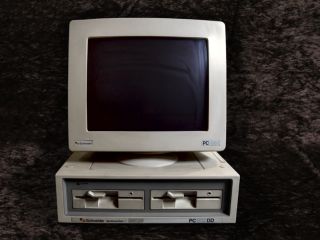
x86 programming for Ms Dos
Computers in CGA , EGA and VGA
The IBM 8086 took the world by storm!
Although inferior to the 68000 - the x86 soon took over, and is the
basis for all the computers we have today...
Starting with the 8086, and soon moving to the 286, 386 and so on...
each iteration has added more commands and power, and along the way
the PC has gained functionality...
|
|
|
 |
In these tutorials, we'll take a look at the early basic
machines, and learn how we can use Assembly to write games that can
be used in MSDos via DosBox!
We'll cover 3 graphics modes...
| CGA |
320x200 4 color (Cyan,Magenta,White or Green,Red,Yellow) |
| EGA |
320x200 16 color fixed palette |
| VGA |
320x200 256 color palette |
|
 |
 |
If you want to learn 8086 get the Cheatsheet! it has all the 8086 commands, It will help you
get started with ASM programming, and let you quickly look up
commands when you get confused! |
 |
Useful Documents
MASM61PROGUIDE
- Microsoft Assembler guide
MASM - Microsoft's
Dos based assembler
80x86 IBM PC and Compatible Computers - Programming guide
8086/186 - Intel CPU manual

ChibiAkumas Tutorials
8086 Hello World Series
8086 Simple Samples
8086 Platform Specific Lessons
8086 SuckHunt Series
CGA color Palette
|
Palette 0 Dark |
Palette 0
Bright |
Palette 1 Dark |
Palette 1 Bright |
| 0 |
|
|
|
|
| 1 |
|
|
|
|
| 2 |
|
|
|
|
| 3 |
|
|
|
|
EGA color Palette
The EGA system uses 16 colors - it's 320x200 can only use a palette of 16
colors (the same colors!)
Each color has a logical number from 0-16, and a Hardware number (used for
palette definitions) from 0-63
| 0
- 0 |
1 - 1 |
2 - 2 |
3 - 3 |
4 - 4 |
5 - 5 |
6 - 20 |
7 - 7 |
| 8
- 56 |
9 - 57 |
10 - 58 |
11 - 59 |
12 - 60 |
13 - 61 |
14 - 62 |
15 - 63 |
EGA Ports
| Port |
AH |
AL |
Purpose |
03C0h
|
%--RGBrgb |
00h |
Palette |
| 03C0h |
%--RGBrgb |
01h |
Palette |
| 03C0h |
%--RGBrgb |
02h |
Palette |
| 03C0h |
%--RGBrgb |
03h |
Palette |
| 03C0h |
%--RGBrgb |
04h |
Palette |
| 03C0h |
%--RGBrgb |
05h |
Palette |
| 03C0h |
%--RGBrgb |
06h |
Palette |
| 03C0h |
%--RGBrgb |
07h |
Palette |
| 03C0h |
%--RGBrgb |
08h |
Palette |
| 03C0h |
%--RGBrgb |
09h |
Palette |
| 03C0h |
%--RGBrgb |
0Ah |
Palette |
| 03C0h |
%--RGBrgb |
0Bh |
Palette |
| 03C0h |
%--RGBrgb |
0Ch |
Palette |
| 03C0h |
%--RGBrgb |
0Dh |
Palette |
| 03C0h |
%--RGBrgb |
0Eh |
Palette |
| 03C0h |
%--RGBrgb |
0Fh |
Palette |
| 03C0h |
%----MMMM |
10h |
Mode Control |
| 03C0h |
%--OOOOOO |
11h |
Overscan |
| 03C0h |
%--DDPPPP |
12h |
Color plane
enable |
| 03C0h |
%----PPPP |
13h |
Horizontal
panning |
| 03C2h |
%IFFS---- |
00h |
Input status
0 register |
| 03C2h |
%VHBDCEc |
01h |
Misc Output
register |
| 03C4h |
%------SA |
00h |
Sequencer
reset |
| 03C4h |
%----CScD |
01h |
Sequence
clocking mode |
| 03C4h |
%----3210 |
02h |
Write mask
register plane n) |
| 03C4h |
%----CCcc |
03h |
Character map
select |
| 03C4h |
%-----OMA |
04h |
Memory mode |
| 03CAh |
%------PP |
|
Graphics 2
position |
| 03CCh |
%------PP |
|
Graphics 1
position |
| 03CEh |
%----3210 |
00h |
In Write mode
0 set bit according to 3CEh |
| 03CEh |
%----3210 |
01h |
In Write mode
0 set bit according to 3CEh |
| 03CEh |
%----3210 |
02h |
In Write mode
0 set bit according to 3CEh |
| 03CEh |
%----3210 |
03h |
In Write mode
0 set bit according to 3CEh |
| 03CEh |
%------PP |
04h |
Read
Bitplane register |
| 03CEh |
%--CORFWW |
05h |
Read/Write
Mode |
| 03CEh |
%----MMOG |
06h |
Graphics Misc |
| 03CEh |
%----3210 |
07h |
Ignore
bitplane register |
| 03CEh |
%BBBBBBBB |
08h |
Bit mask
register |
| 03D4h |
%HHHHHHHH |
00h |
CRTC
Horizontal Total |
| 03D4h |
%HHHHHHHH |
01h |
CRTC
Horizontal Display End |
| 03D4h |
%HHHHHHHH |
02h |
CRTC Start
Horiz Blanking Register |
| 03D4h |
%-CCHHHHH |
03h |
CRTC End
Horiz Blanking Register |
| 03D4h |
%HHHHHHHH |
04h |
CRTC Start
Horiz Retrace Register |
| 03D4h |
%DCCHHHHH |
05h |
CRTC End
Horiz Retrace Register |
| 03D4h |
%VVVVVVVV |
06h |
CRTC Vertical
Blank Total |
| 03D4h |
%---LSEDT |
07h |
CRTC Overflow
register |
| 03D4h |
%---LLLLL |
08h |
CRTC Preset
Row Scan Register |
| 03D4h |
%---LLLLL |
09h |
CRTC Maximum
scan line register |
| 03D4h |
%---CCCCC |
0Ah |
CRTC Cursor
Start Reg |
| 03D4h |
%-DDCCCCC |
0Bh |
CRTC Cursor
End Reg |
| 03D4h |
%AAAAAAAA |
0Ch |
CRTC Cursor
Start Address High Reg |
| 03D4h |
%AAAAAAAA |
0Dh |
CRTC Cursor
Start Address Low Reg |
| 03D4h |
%CCCCCCCC |
0Eh |
CRTC Cursor
Location High Reg |
| 03D4h |
%CCCCCCCC |
0Fh |
CRTC Cursor
Location Low Reg |
| 03D4h |
%VVVVVVVV |
10h |
CRTC Vertical
Retrace Start Reg |
| 03D4h |
%PPPPPPPP |
11h |
CRTC Light
Pen Low Register (Read) |
| 03D4h |
%--ICVVVV |
11h |
CRTC Vertical
Retrace End Reg (Write) |
| 03D4h |
%VVVVVVVV |
12h |
CRTC Virtical
Display End Register |
| 03D4h |
%OOOOOOOO |
13h |
CRTC Offset
Register |
| 03D4h |
%---UUUUU |
14h |
CRTC
Underline location Reg |
| 03D4h |
%VVVVVVVV |
15h |
CRTC Start
Vert Blanking Register |
| 03D4h |
%---VVVVV |
16h |
CRTC End Vert
Blanking Register |
| 03D4h |
%RWBDCSHc |
17h |
CRTC: Mode
control register |
| 03D4h |
%LLLLLLLL |
18h |
CRTC: Line
Compare Register |
| 03DAh |
%--CCVLlR |
|
Input Status
1 Register (Read) |
| 03DAh |
%------OO |
|
Feature
Control Register (Write) |
Screen Layouts
CGA is a 2bpp screen mode, it's memory is at B800:0000h
EGA use 4 bitplanes, it's address is A000:0000... to change the bitplanes
we need to OUT to 03C4h
VGA is a 8bpp screen mode, it's memory is at A000:0000h
|
|
|
|
|
Bits |
| Screen
Mode |
Bits
per pixel |
Pixels
per byte |
Address |
Plane
Mask |
7 |
6 |
5 |
4 |
3 |
2 |
1 |
0 |
| CGA
- 4 |
2 bpp |
4 |
B800:0000h |
|
b1 |
b0 |
b1 |
b0 |
b1 |
b0 |
b1 |
b0 |
| EGA - 13 |
4
bitplanes |
8 |
A000:0000h |
out 03c4h,0102h |
p0-b7 |
p0-b6 |
p0-b5 |
p0-b4 |
p0-b3 |
p0-b2 |
p0-b1 |
p0-b0 |
| out 03c4h,0202h |
p1-b7 |
p1-b6 |
p1-b5 |
p1-b4 |
p1-b3 |
p1-b2 |
p1-b1 |
p1-b0 |
| out 03c4h,0302h |
p2-b7 |
p2-b6 |
p2-b5 |
p2-b4 |
p2-b3 |
p2-b2 |
p2-b1 |
p2-b0 |
| out 03c4h,0402h |
p3-b7 |
p3-b6 |
p3-b5 |
p3-b4 |
p3-b3 |
p3-b2 |
p3-b1 |
p3-b0 |
| out 03c4h,0F02h |
All-b7 |
All-b6 |
All-b5 |
All-b4 |
All-b3 |
All-b2 |
All-b1 |
All-b0 |
| VGA |
8bpp |
1 |
A000:0000h |
|
b7 |
b6 |
b5 |
b4 |
b3 |
b2 |
b1 |
b0 |
Beeper Sound Ports
| Port |
Modes |
Purpose |
Bits |
Notes |
| 0040 |
RW |
PIT counter
0, counter divisor (XT, AT, PS/2) |
CCCCCCCC |
Send L/H Pair |
| 0041 |
RW |
PIT counter
1, RAM refresh counter (XT, AT) |
CCCCCCCC |
Send L/H Pair |
| 0042 |
RW |
PIT counter
2, cassette & speaker (XT, AT, PS/2) |
CCCCCCCC |
Send L/H Pair |
| 0043 |
RW |
PIT mode
port, control word register for counters 0-2 |
CCAAMMMS |
C=Counter
select (0-2), A=counter Access, M=counter Mode (0-5), S=counter
Style (0=16 bit 1=BCD) |
| 0061 |
W |
PPI
Programmable Peripheral Interface 8255 (XT only) |
----PPST
|
P= parity
checks S=Speaker enable T=speaker Timer enable |
| 0061 |
R |
KB controller
port B control register (ISA, EISA) |
EETDPPST |
E=errors
T=Timer D=Detect P= parity checks S=Speaker enable T=speaker Timer
enable |
Adlib OPL2 Registers
The ADLIB sound card usesd OPL2, which is also supported by the
full SoundBlaster range, it uses a range of registers to make its
sounds, each sound channel is formed by a combination of two Operators
NOTE: OPL3 doubled the number of registers, with an 'Advanced'
set... for simplicity (and my sanity) we'll just be covering the basic
OPL2 set, which are supported by OPL3 as well!
There are a total of up to 9 sound channels... each sound is the
combination of two "OP signals"... we should set both to get a sound
from a channel! How the OPs are combined is defined by bit 0 of
registers C0h-C8h... see the pdf documents for more info.
| Channel
Signal |
1 |
2 |
3 |
4 |
5 |
6 |
7
(Ryt) |
8
(Ryt) |
9
(Ryt) |
| OP1 Slot 1
Signal |
1 |
|
2 |
|
3 |
|
7 |
|
8 |
|
9 |
|
13 |
|
14 |
|
15 |
|
| OP2 Slot 2
Signal |
|
4 |
|
5 |
|
6 |
|
10 |
|
11 |
|
12 |
|
16 |
|
17 |
|
18 |
Register settings
for slot |
20 |
|
21 |
|
22 |
|
28 |
|
29 |
|
2A |
|
30 |
|
31 |
|
32 |
|
|
23 |
|
24 |
|
25 |
|
2B |
|
2C |
|
2D |
|
33 |
|
34 |
|
35 |
| 40 |
|
41 |
|
42 |
|
48 |
|
49 |
|
4A |
|
50 |
|
51 |
|
52 |
|
|
43 |
|
44 |
|
45 |
|
4B |
|
4C |
|
4D |
|
53 |
|
54 |
|
55 |
| 60 |
|
61 |
|
62 |
|
68 |
|
69 |
|
6A |
|
70 |
|
71 |
|
72 |
|
|
63 |
|
64 |
|
65 |
|
6B |
|
6C |
|
6D |
|
73 |
|
74 |
|
75 |
| 80 |
|
81 |
|
82 |
|
88 |
|
89 |
|
8A |
|
90 |
|
91 |
|
92 |
|
|
83 |
|
84 |
|
85 |
|
8B |
|
8C |
|
8D |
|
93 |
|
94 |
|
95 |
| E0 |
|
E1 |
|
E2 |
|
E8 |
|
E9 |
|
EA |
|
F0 |
|
F1 |
|
F2 |
|
|
E3 |
|
E4 |
|
E5 |
|
EB |
|
EC |
|
ED |
|
F3 |
|
F4 |
|
F5 |
Register settings for
the channel |
A0 |
A1 |
A2 |
A3 |
A4 |
A5 |
A6 |
A7 |
A8 |
| B0 |
B1 |
B2 |
B3 |
B4 |
B5 |
B6 |
B7 |
B8 |
| C0 |
C1 |
C2 |
C3 |
C4 |
C5 |
C6 |
C7 |
C8 |
Channels 7,8,9 can be toggled as Rhythm effects by setting bit 5 of
0BDh to 1
In this mode bits 0-4 of 0BDh will 'fire' the effects... each
effect uses some of the signal slots, the registers for this slot will
need to be set up as usual
BDh bits %DDRBSTCH
R=Rhythm enabled (channel 7-9 no
longer normal FM sound)
Bit / Rhythm sound
|
OP / Signal Slots used
|
| B=Bass |
13 & 16 |
| S=Snare |
17 |
| T=Tom |
15 |
| C=Cymbal |
18 |
| H=Hihat |
14 |
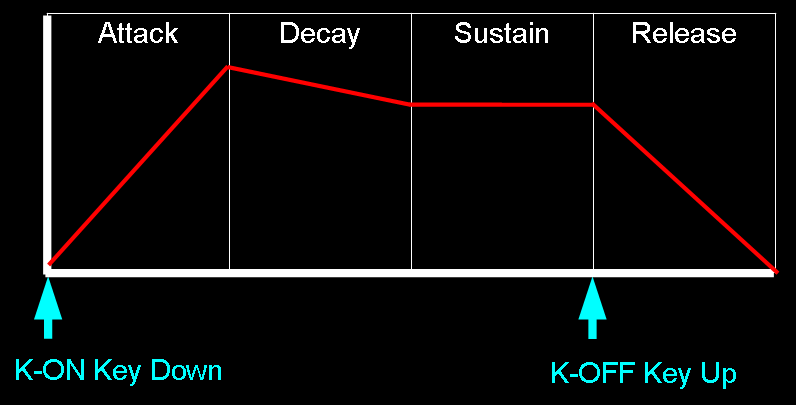
Sound over time
The OPs define how the sound level changes over time... K-On and K-Off
mimic the way piano keys work.. when the key is struck the sound will
start (Attack), and fade slowly (Decay) to a constant tone (Sustain), when
the key is lifted, it will fade quickly (Release)
Adlib OPL2 Registers and bits
| Register |
Details |
Bits |
Details |
| 01h |
Test |
--WDDDDD |
W=Wave select
Enable (opl2) / D=Test Data |
| 02h |
Timer 1
Setting 80-20.4us |
TTTTTTTT |
T=Timer |
| 03h |
Timer 2
Setting 320-82 us |
TTTTTTTT |
T=Timer |
| 04h |
Timer 1/2
control |
RMM---SS |
R=Reset
M=Mask S=? |
| 08h |
Speech Synth
/ Keyboard Split NoteSel |
CS------ |
C=CSM Speech
synth mode / S=note Select |
| 20h
- 35h |
Multi / Key
Scale Rate / EG-Type Tone / Vibrato / AM modulation |
AVEKMMMM |
A=AM V=VIB
E=EG-Typ K=KSR M=Multiple |
| 40h
- 55h |
Total Level /
Key Scale Level |
KKTTTTTT |
K=KeyScaleLevel
T=Total Level (0=loud) |
| 60h
- 75h |
Decay Rate /
Attack Rate |
AAAADDDD |
A=Attack
(0=slow) D=Decay (0=slow) |
| 88h
- 95h |
Release Rate
/ Sustain Level |
SSSSRRRR |
S=Sustain
(0=loud) R=Release (0=slow) |
| A0h
- A8h |
F number |
FFFFFFFF |
F=Fnumber L |
| B0h
- B8h |
Block / K-ON |
--KBBBFF |
F=Fnumber H
B=Block K=K-on |
| BDh |
Rhythm mode
(Chn 7-9) / Vibrato Depth / AM Depth |
DDRBSTCH |
D=Depth
(AM/VIB) R=Rhythm
B=Bass(13,16) S=Snare(17) T=Tom(15) C=Cymbal(18)
H=Hihat(14) |
| C0h
- C8h |
FeedBack
factor / C=Connection sine/fm |
----FFFC |
F=Feedback
C=Connection (Op combination mode)
|
| E0h
- F5h |
Wave Select |
------WW |
WW=Wave
Select |
|
|
|
|
| (Address
port Read) |
Status Reg |
IFF----- |
I=IRQ F=Flag |
Useful ADLIB docs:
yamaha_ymf262
- OPL3 Manual (Adlib Gold / SB16)
YM3812 - OPL2
Manual (adlib)
ym3625 -
OPL(1) manual
Soundblaster -
Soundblaster programming guide
Adlib
Programming - Adlib programming guide
