| Opcode |
Instruction |
Function |
Example |
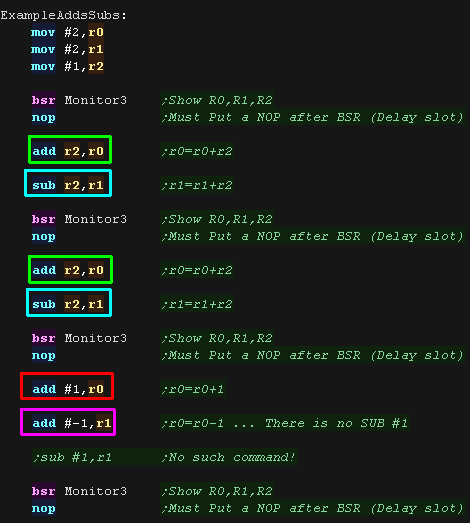
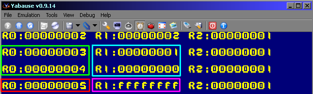
| ADD Rm,Rn |
ADD Binary |
Rm + Rn → Rn |
ADD R0,R1 |
| ADD #imm,Rn |
ADD Binary |
Rn + #imm → Rn |
ADD #H'01,R2 |
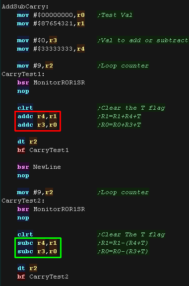
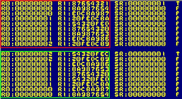
| ADDC Rm,Rn |
ADD with Carry |
Rn + Rm + T → Rn,
carry → T |
ADDC R3,R1 |
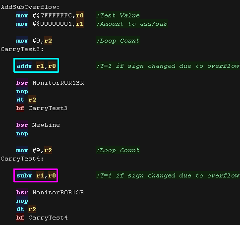
| ADDV Rm,Rn |
ADD with V Flag Overflow Check |
Rn + Rm → Rn,
overflow → T |
ADDV R0,R1 |
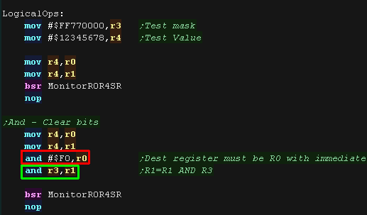
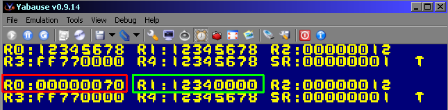
| AND Rm,Rn |
AND Logical |
Rn & Rm → Rn |
AND R0,R1 |
| AND #imm,R0 |
AND Logical |
R0 & imm → R0 |
AND #H'0F,R0 |
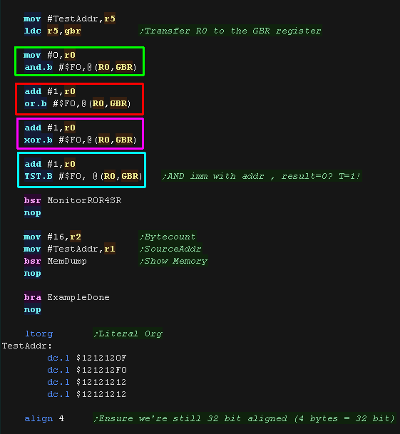
| AND.B #imm,@(R0,GBR) |
AND Logical |
(R0 + GBR) & imm
→ (R0 + GBR) |
AND.B #H'80,@(R0,GBR) |
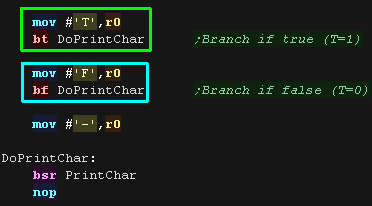
| BF label |
Branch if False |
When T = 0, disp � 2 + PC → PC;
When T = 1, nop |
BF TRGET_F |
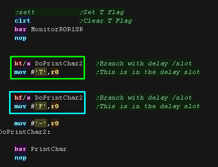
| BF/S label |
Branch if False with Delay Slot |
When T = 0, disp � 2+ PC → PC;
When T = 1, nop |
BF/S TRGET_F |
| BRA label |
Branch |
disp � 2 + PC → PC |
BRA TRGET |
| BRAF @Rn |
Branch Far |
Rn + PC → PC |
|
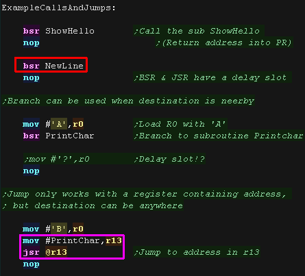
| BSR label |
Branch to Subroutine |
PC → PR, disp � 2+ PC → PC |
BSR TRGET |
| BSRF @Rn |
Branch to Subroutine Far |
PC → PR, Rn + PC → PC |
BRSF R0 |
| BT label |
Branch if True |
When T = 1, disp � 2 + PC → PC;
When T = 0, nop |
BT TRGET_T |
| BT/S label |
Branch if True with Delay Slot |
When T = 1,disp � 2 + PC → PC;
When T = 0, nop |
BT/S TARGET_T |
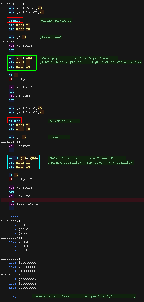
| CLRMAC |
Clear MAC Register |
0 → MACH, MACL |
CLRMAC |
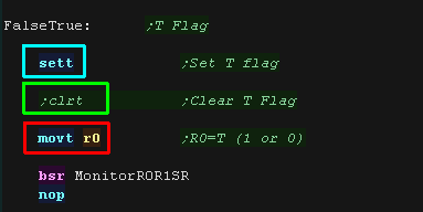
| CLRT |
Clear T Bit |
0 → T |
CLRT |
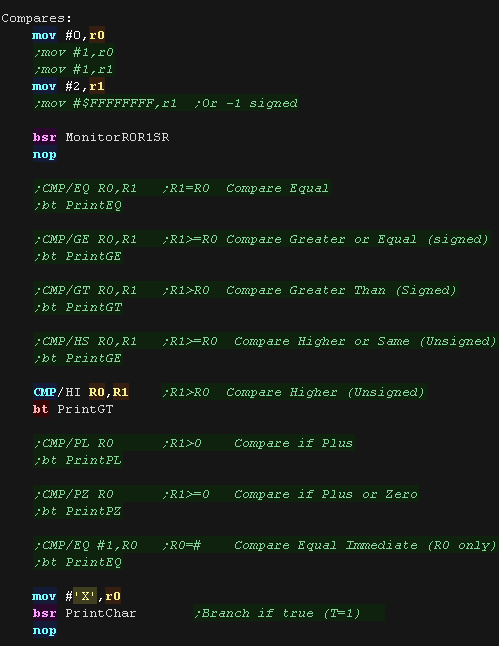
| CMP/EQ Rm,Rn |
Compare Equal |
When Rn = Rm,1 → T |
|
| CMP/GE Rm,Rn |
Compare Greater or Equal (signed) |
When signed and Rn � Rm, 1 → T |
CMP/GE R0,R1 |
| CMP/GT Rm,Rn |
Compare Greater Than (Signed) |
When signed and Rn > Rm, 1 → T |
|
| CMP/HI Rm,Rn |
Compare Higher (Unsigned) |
When unsigned and Rn > Rm, 1 → T |
|
| CMP/HS Rm,Rn |
Compare Higher or Same (Unsigned) |
When unsigned and Rn � Rm, 1 → T |
CMP/HS R0,R1 |
| CMP/PL Rn |
Compare if Plus |
When Rn > 0, 1 → T |
|
| CMP/PZ Rn |
Compare if Plus or Zero |
When Rn � 0, 1 → T |
|
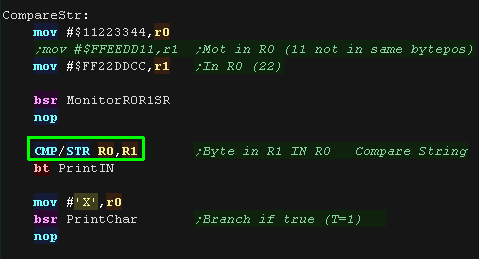
| CMP/STR Rm,Rn |
Compare String |
When byte in Rn = byte in Rm, 1 → T |
CMP/STR R2,R3 |
| CMP/EQ #imm,R0 |
Compare Equal Immediate |
When R0 = imm, 1 → T |
|
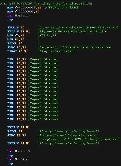
| DIV0S Rm,Rn |
Divide Step 0 as Signed |
MSB of Rn → Q,
MSB of Rm → M,M^Q → T |
DIV0S R0,R1 |
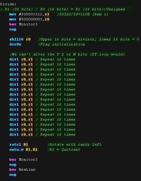
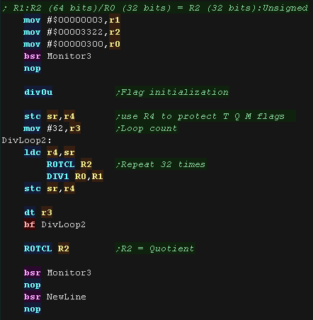
| DIV0U |
Divide Step 0 as Unsigned |
0 → M/Q/T |
DIV0U |
| DIV1 Rm,Rn |
Divide 1 Step |
1 step division (Rn � Rm) |
DIV1 R0,R1 |
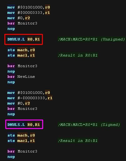
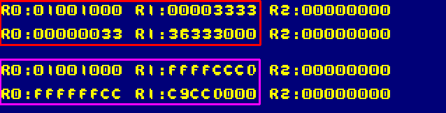
| DMULS.L Rm,Rn |
Double-Length Multiply as Signed |
With sign,Rn � Rm
→MACH, MACL |
DMULS.L R0,R1 |
| DMULU.L Rm,Rn |
Double-Length Multiply as Unsigned |
Without sign,Rn � Rm
→MACH, MACL |
DMULU.L R0,R1 |
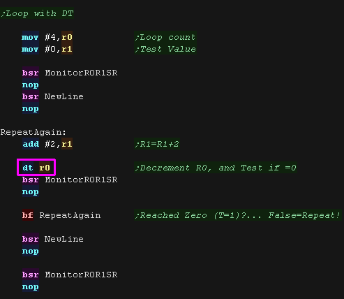
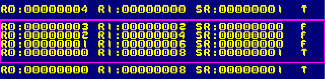
| DT Rn |
Decrement and Test (DJNZ) |
Rn � 1 → Rn;When Rn is 0,1 → T,
when Rn is nonzero, 0 → T |
DT R5 |
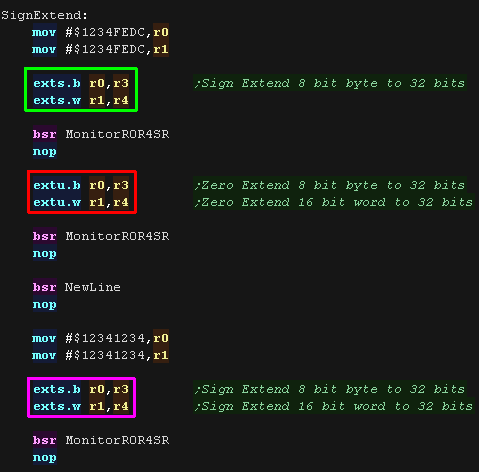
| EXTS.B Rm,Rn |
Extend as Signed |
Sign-extend Rm from byte → Rn |
EXTS.B R0,R1 |
| EXTS.W Rm,Rn |
Extend as Signed |
Sign-extend Rm from word → Rn |
EXTS.W R0,R1 |
| EXTU.B Rm,Rn |
Extend as Unsigned |
Zero-extend Rm from byte → Rn |
EXTU.B R0,R1 |
| EXTU.W Rm,Rn |
Extend as Unsigned |
Zero-extend Rm from word → Rn |
EXTU.W R0,R1 |
| JMP @Rn |
Jump |
Rn → PC |
JMP @R0 |
| JSR @Rn |
Jump to Subroutine |
PC → PR, Rn → PC |
JSR @R0 |
| LDC Rm,SR |
Load to Control Register |
Rm → SR |
LDC R0,SR |
| LDC Rm,GBR |
Load to Control Register |
Rm → GBR |
|
| LDC Rm,VBR |
Load to Control Register |
Rm → VBR |
|
| LDC.L @Rm+,SR |
Load to Control Register |
(Rm) → SR, Rm + 4 → Rm |
|
| LDC.L @Rm+,GBR |
Load to Control Register |
(Rm) → GBR, Rm + 4 → Rm |
LDC.L @R15+,GBR |
| LDC.L @Rm+,VBR |
Load to Control Register |
(Rm) → VBR, Rm + 4 → Rm |
|
| LDS Rm,MACH |
Load to System Register |
Rm → MACH |
|
| LDS Rm,MACL |
Load to System Register |
Rm → MACL |
|
| LDS Rm,PR |
Load to System Register |
Rm → PR |
LDS R0,PR |
| LDS.L @Rm+,MACH |
Load to System Register |
(Rm) → MACH,Rm + 4 → Rm |
|
| LDS.L @Rm+,MACL |
Load to System Register |
(Rm) → MACL,Rm + 4 → Rm |
LDS.L @R15+,MACL |
| LDS.L @Rm+,PR |
Load to System Register |
(Rm) → PR,Rm + 4 → Rm |
|
| MAC.L @Rm+,@Rn+ |
Multiply and Accumulate Calculation Long |
Signed operation
(Rn) � (Rm) + MAC→ MAC |
MAC.L @R0+,@R1+ |
MAC.W @Rm+,@Rn+
MAC @Rm+,@Rn+ |
Multiply and Accumulate Calculation Word |
With sign, (Rn) � (Rm) + MAC
→ MAC |
MAC.W @R0+,@R1+ |
| MOV Rm,Rn |
Move Data |
Rm → Rn |
MOV R0,R1 |
| MOV.B Rm,@Rn |
Move Data |
Rm → (Rn) |
|
| MOV.W Rm,@Rn |
Move Data |
Rm → (Rn) |
MOV.W R0,@R1 |
| MOV.L Rm,@Rn |
Move Data |
Rm → (Rn) |
|
| MOV.B @Rm,Rn |
Move Data |
(Rm) → sign extension → Rn |
|
| MOV.W @Rm,Rn |
Move Data |
(Rm) → sign extension → Rn |
|
| MOV.L @Rm,Rn |
Move Data |
(Rm) → Rn |
|
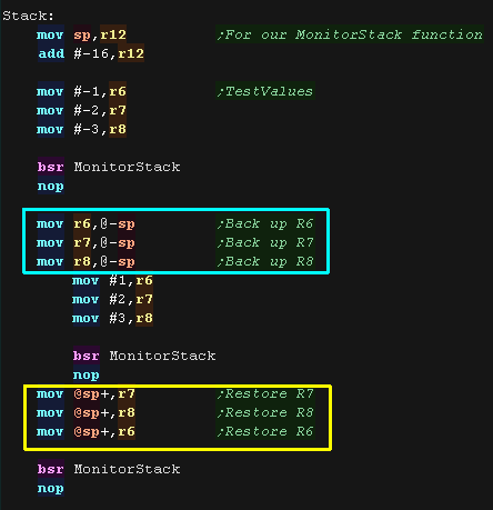
| MOV.B Rm,@�Rn |
Move Data |
Rn � 1 → Rn,Rm → (Rn) |
|
| MOV.W Rm,@�Rn |
Move Data |
Rn � 2 → Rn,Rm → (Rn) |
MOV.W R0,@�R1 |
| MOV.L Rm,@�Rn |
Move Data |
Rn � 4 → Rn,Rm → (Rn) |
|
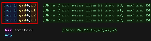
| MOV.B @Rm+,Rn |
Move Data |
(Rm) → sign ext → Rn,Rm + 1 → Rm |
MOV.B @R0,R1 |
| MOV.W @Rm+,Rn |
Move Data |
(Rm) → sign ext → Rn, Rm + 2 → Rm |
|
| MOV.L @Rm+,Rn |
Move Data |
(Rm) → Rn, Rm + 4 → Rm |
MOV.L @R0+,R1 |
| MOV.B Rm,@(R0,Rn) |
Move Data |
Rm → (R0 + Rn) |
MOV.B R1,@(R0,R2) |
| MOV.W Rm,@(R0,Rn) |
Move Data |
Rm → (R0 + Rn) |
|
| MOV.L Rm,@(R0,Rn) |
Move Data |
Rm → (R0 + Rn) |
|
| MOV.B @(R0,Rm),Rn |
Move Data |
(R0 + Rm) → sign extension → Rn |
|
| MOV.W @(R0,Rm),Rn |
Move Data |
(R0 + Rm) → sign extension → Rn |
MOV.W @(R0,R2),R1 |
| MOV.L @(R0,Rm),Rn |
Move Data |
(R0 + Rm) → Rn |
|
| MOV #imm,Rn |
Move Immediate Data |
imm → sign extension → Rn |
MOV #H'80,R1 |
| MOV.W @(disp,PC),Rn |
Move Immediate Data |
(disp � 2 + PC) → sign ext → Rn |
MOV.W IMM,R2 |
| MOV.L @(disp,PC),Rn |
Move Immediate Data |
(disp � 4 + PC) → Rn |
MOV.L @(4,PC),R3 |
| MOV.B @(disp,GBR),R0 |
Move Peripheral Data |
(disp + GBR) → sign ext → R0 |
|
| MOV.W @(disp,GBR),R0 |
Move Peripheral Data |
(disp � 2 + GBR) → sign ext → R0 |
|
| MOV.L @(disp,GBR),R0 |
Move Peripheral Data |
(disp � 4 + GBR) → R0 |
MOV.L @(2,GBR),R0 |
| MOV.B R0,@(disp,GBR) |
Move Peripheral Data |
R0 → (disp + GBR) |
MOV.B R0,@(1,GBR) |
| MOV.W R0,@(disp,GBR) |
Move Peripheral Data |
R0 → (disp � 2 + GBR) |
|
| MOV.L R0,@(disp,GBR) |
Move Peripheral Data |
R0 → (disp � 4 + GBR) |
|
| MOV.B R0,@(disp,Rn) |
Move Structure Data |
R0 → (disp + Rn) |
|
| MOV.W R0,@(disp,Rn) |
Move Structure Data |
R0 → (disp � 2 + Rn) |
|
| MOV.L Rm,@(disp,Rn) |
Move Structure Data |
Rm → (disp � 4 + Rn) |
MOV.L R0,@(H'F,R1) |
| MOV.B @(disp,Rn),R0 |
Move Structure Data |
(disp + Rn) → sign extension → R0 |
|
| MOV.W @(disp,Rn),R0 |
Move Structure Data |
(disp � 2 + Rn) → sign extension → R0 |
|
| MOV.L @(disp,Rm),Rn |
Move Structure Data |
(disp � 4 + Rm) → Rn |
MOV.L @(2,R0),R1 |
| MOVA @(disp,PC),R0 |
Move Effective Address |
disp � 4 + PC → R0 |
MOVA @(0,PC),R0 |
| MOVT Rn |
Move T Bit |
T → Rn |
MOVT R0 |
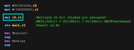
MUL.L Rm,Rn
MUL Rm,Rn |
Multiply Long |
Rn � Rm → MACL |
MULL R0,R1 |
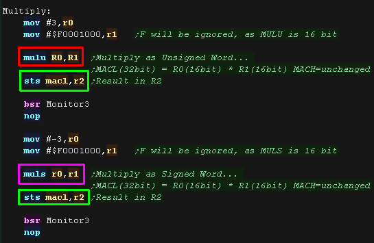
MULS.W Rm,Rn
MULS Rm,Rn |
Multiply as Signed Word |
Signed operation, Rn � Rm → MACL |
MULS R0,R1 |
MULU.W Rm,Rn
MULU Rm,Rn |
Multiply as Unsigned Word |
Unsigned, Rn � Rm → MACL |
MULU R0,R1 |
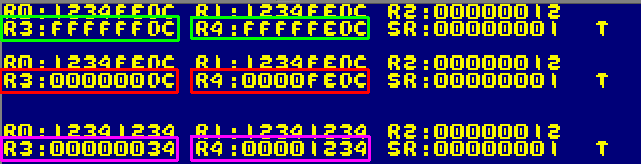
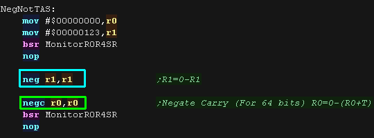
| NEG Rm,Rn |
Negate |
0 � Rm → Rn |
NEG R0,R1 |
| NEGC Rm,Rn |
Negate with Carry |
0 � Rm � T → Rn, Borrow → T |
NEGC R1,R1 |
| NOP |
No operation |
No operation |
NOP |
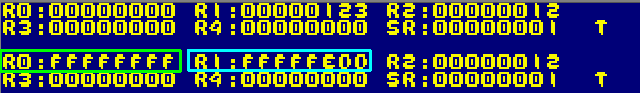
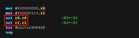
| NOT Rm,Rn |
NOT�Logical Complement |
~Rm → Rn |
NOT R0,R1 |
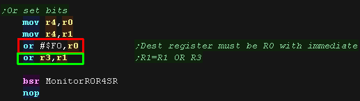
| OR Rm,Rn |
OR Logical |
Rn |
1 |
| OR #imm,R0 |
OR Logical |
R0 |
1 |
| OR.B #imm,@(R0,GBR) |
OR Logical |
(R0 + GBR) |
3 |
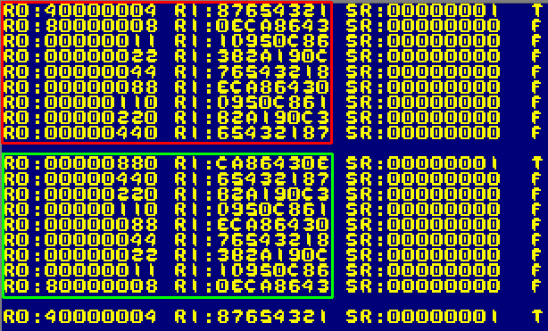
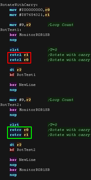
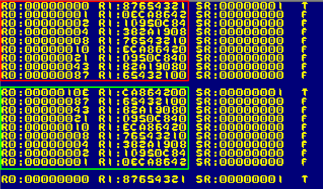
| ROTCL Rn |
Rotate with Carry Left |
T ← Rn ← T |
ROTCL R0 |
| ROTCR Rn |
Rotate with Carry Right |
T → Rn → T |
ROTCR R0 |
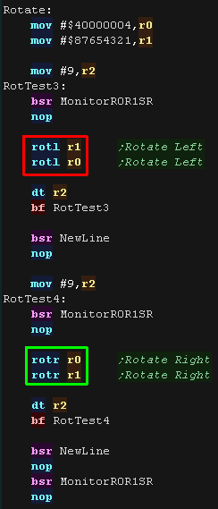
| ROTL Rn |
Rotate Left |
T ← Rn ← MSB |
ROTL R0 |
| ROTR Rn |
Rotate Right |
LSB → Rn → T |
ROTR R0 |
| RTE |
Return from Exception |
Delayed branch, Stack area → PC/SR |
RTE |
| RTS |
Return from Subroutine |
Delayed branch, PR → PC |
RTS |
| SETT |
Set T Bit |
1 → T |
SETT |
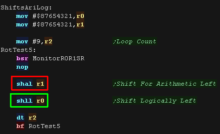
| SHAL Rn |
Shift Arithmetic Left 1 Bit with carry |
T ← Rn ← 0 |
SHAL R0 |
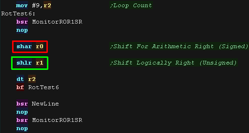
| SHAR Rn |
Shift Arithmetic Right 1 Bit with carry |
MSB → Rn → T |
SHAR R0 |
| SHLL Rn |
Shift Logical Left 1 Bit with carry |
T ← Rn ← 0 |
SHLL R0 |
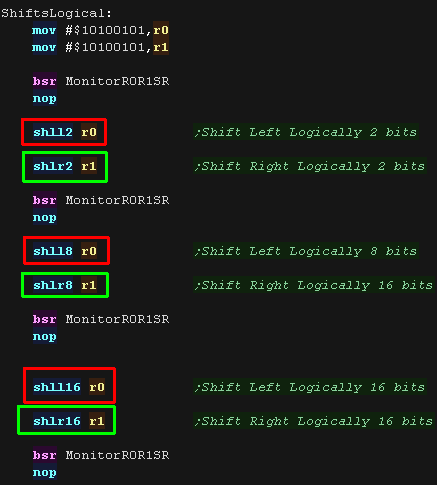
| SHLL2 Rn |
Shift Logical Left 2 Bits |
Rn << 2 → Rn |
SHLL2 R0 |
| SHLL8 Rn |
Shift Logical Left 8 Bits |
Rn << 8 → Rn |
SHLL8 R0 |
| SHLL16 Rn |
Shift Logical Left 16 Bits |
Rn << 16 → Rn |
SHLL16 R0 |
| SHLR Rn |
Shift Logical Right 1 Bit with carry |
0 → Rn → T |
SHLR R0 |
| SHLR2 Rn |
Shift Logical Right 2 Bits |
Rn>>2 → Rn |
SHLR2 R0 |
| SHLR8 Rn |
Shift Logical Right 16 Bits |
Rn>>8 → Rn |
SHLR8 R0 |
| SHLR16 Rn |
Shift Logical Right 16 Bits |
Rn>>16 → Rn |
SHLR16 R0 |
| SLEEP |
Sleep |
Sleep |
SLEEP |
| STC SR,Rn |
Store Control Register |
SR → Rn |
STC SR,R0 |
| STC GBR,Rn |
Store Control Register |
GBR → Rn |
|
| STC VBR,Rn |
Store Control Register |
VBR → Rn |
|
| STC.L SR,@-Rn |
Store Control Register |
Rn � 4 → Rn, SR → (Rn) |
|
| STC.L GBR,@-Rn |
Store Control Register |
Rn � 4 → Rn, GBR → (Rn) |
STC.L GBR,@-R15 |
| STC.L VBR,@-Rn |
Store Control Register |
Rn � 4 → Rn, VBR → (Rn) |
|
| STS MACH,Rn |
Store System Register |
MACH → Rn |
STS MACH,R0 |
| STS MACL,Rn |
Store System Register |
MACL → Rn |
|
| STS PR,Rn |
Store System Register |
PR → Rn |
|
| STS.L MACH,@�Rn |
Store System Register |
Rn � 4 → Rn,MACH → (Rn) |
|
| STS.L MACL,@�Rn |
Store System Register |
Rn � 4 → Rn,MACL → (Rn) |
|
| STS.L PR,@�Rn |
Store System Register |
Rn � 4 → Rn,PR → (Rn) |
STS.L PR,@�R15 |
| SUB Rm,Rn |
Subtract Binary |
Rn � Rm → Rn |
SUB R0,R1 |
| SUBC Rm,Rn |
Subtract with Carry |
Rn � Rm� T → Rn, Borrow → T |
SUBC R3,R1 |
| SUBV Rm,Rn |
Subtract with V Flag Underflow Check |
Rn � Rm → Rn, underflow → T |
SUBV R0,R1 |
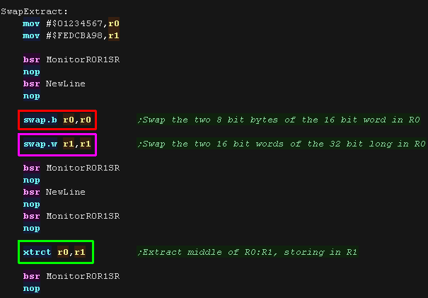
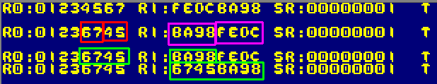
| SWAP.B Rm,Rn |
Swap Register Halves |
Rm → Swap upper and lower halves
of lower 2 bytes → Rn |
SWAP.B R0,R1 |
| SWAP.W Rm,Rn |
Swap Register Halves |
Rm → Swap upper and
lower word → Rn |
SWAP.W R0,R1 |
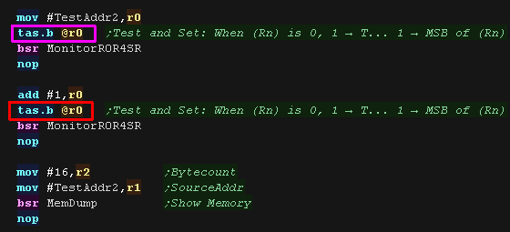
| TAS.B @Rn |
Test and Set |
When (Rn) is 0, 1 → T,
1 → MSB of (Rn) |
TAS.B @R7 |
| TRAPA #imm |
Trap Always |
PC/SR → Stack area,
(imm � 4 + VBR) → PC |
TRAPA #H'20 |
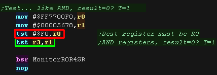
| TST Rm,Rn |
Test Logical |
Rn & Rm, when result is 0, 1 → T |
TST R0,R0 |
| TST #imm,R0 |
Test Logical |
R0 & imm, when result is 0, 1 → T |
TST #H'80,R0 |
| TST.B #imm, @(R0,GBR) |
Test Logical |
(R0 + GBR) & imm,
when result is 0, 1 → T |
TST.B #H'A5,@(R0,GBR) |
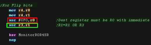
| XOR Rm,Rn |
Exclusive OR Logical |
Rn ^ Rm → Rn |
XOR R0,R1 |
| XOR #imm,R0 |
Exclusive OR Logical |
R0 ^ imm → R0 |
XOR #H'F0,R0 |
| XOR.B #imm,@(R0,GBR) |
Exclusive OR Logical |
(R0 + GBR) ^ imm → (R0 + GBR) |
XOR.B #H'A5,@(R0,GBR) |
| XTRCT Rm,Rn |
Extract |
Rm: Center 32 bits of Rn → Rn |
XTRCT R0,R1 |