
 |
Lesson
P1 - Bitmap graphics and Palette definitions on Risc OS Lets start with RISC-OS... we'll learn how to enable graphics mode, and draw bitmap graphics to the screen. Let's make a start! |
 |
 |
 |
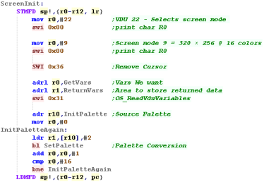
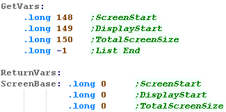
| To turn on the screen we'll use VDU commands... These are 'control characters' we print to the 'screen' (They never actually appear)... We Use SWI 0 to do this. We write 22 (VDU 22) to the screen to select mode, we want Mode 9 - this is 320x256 with 16 colors - so we write 9 next The screen will have a blinking cursor, we use SWI 0x36 to turn it off Next we need to get the address of the screen, we use SWI 0x31 to get the details of the screen, we pass a bank of parameter numbers that we want, and get back the address of the screen in 'ScreenStart' |
  |
 |
There
are a wide range of screen modes available, but we'll only be
using 9!... the 256 color mode is a little weird as it uses 64
base colors with different brightnesses, so you'll probably find
this 16 color mode easier. If you want all the details take a look here! |
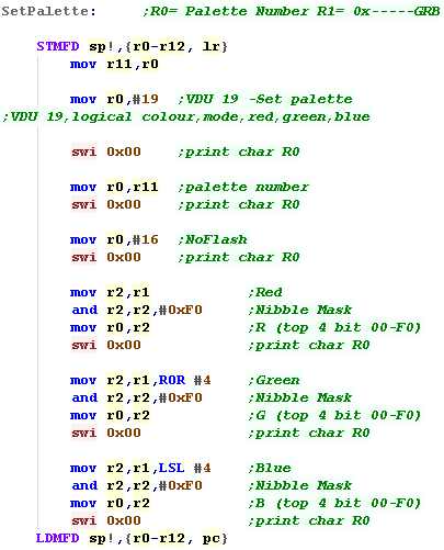
| We're going to set the palette... RiscOS uses 1 nibble per color (4 bit per channel) | 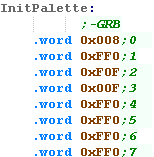 |
| When we want to set a palette entry we use VDU 19... we write
control code 19 to the screen with SWI 0. We write the palette entry number... Next we set the flashing mode (16 = turns it off)... The top nibble of the next3 writes is the Red, Green then Blue part |
 |
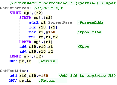
| When we want to draw to the screen, we'll first want to take our
X,Y screen position (in R1,R2) and convert them to a memory
address (returned in R10) As the screen is 320 pixels wide, and 2 pixels are in a single byte, The formula for calculating an address is ScreenAddr = ScreenBase + (Ypos*160) + Xpos We got 'ScreenAddr' when we turned the screen on. When we want to move down a line we add 160 to the screen address. |
 |
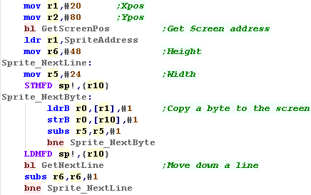
| When we want to draw to the screen, we calculate the screen
address, and copy each byte of the line to the screen, We then move down the screen, and repeat until the sprite is done. |
 |
| The sprite data will be included from a file... As the screen is 4bpp in linear format, each nibble in the file will define the color of a pixel | 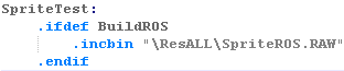 |
| Here is the result! | 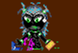 |
| Want to create a valid file? you can use my AkuSprite Editor, it's free and open source, and included in the sources file. | 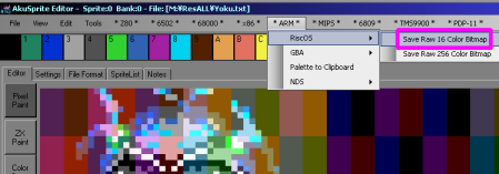 |
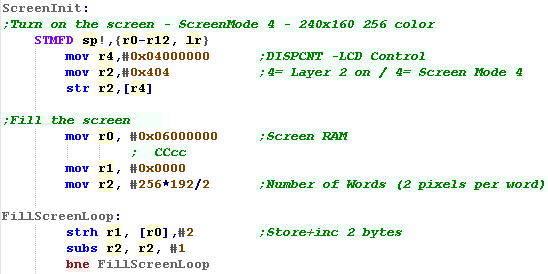
| OK, First we need to set up our screen... we're going to use
'Screen mode 3'... this gives a 16pp bitmap screen (2 bytes per
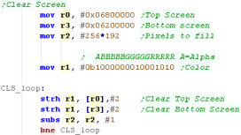
pixel) at ram address 0x06000000 This screen mode only works on Background Layer 2 To turn it on we need to set graphics register x04000000 - bits 0-2 are the Screen mode, bit 10 turns on Background 2 Once the screen is on, we'll fill the screen! The screen starts at 0x06000000 and has 256x192 pixels... where each pixel takes 2 bytes in the format 'ABBBBBGGGGGRRRRR'... with 1 Alpha bit and 5 Blue, Green and Red bits |
 |
 |
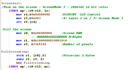
This screen
mode uses 2 bytes (a Half-Word) per pixel... but whatever screen
mode you use, you need to make sure you write to the screen in
WORDS - Writing individual bytes to the screen - even in 256
color mode will not work! |
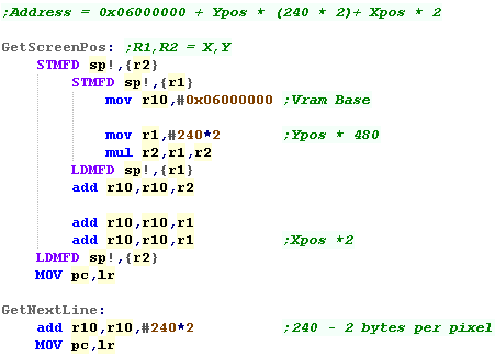
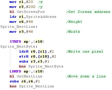
| When we want to draw to the screen we need to calculate the ram
address.. The screen is 240x192 pixels - each pixel is 2 bytes, and our screen base is 0x06800000 Therefore our screen formula is: Address = 0x06000000 + (Ypos * 240 * 2)+ Xpos * 2 When we want to move down the screen, we just add 480 to the current screen address. |
 |
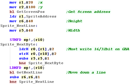
| When we want to draw to the screen, we calculate the screen
address, and copy each byte of the line to the screen, We then move down the screen, and repeat until the sprite is done. |
 |
| We include the bitmap from a file | 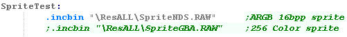 |
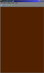
| Here is the result! |  |
| Want to create a valid file? you can use my AkuSprite Editor, it's free and open source, and included in the sources file. | 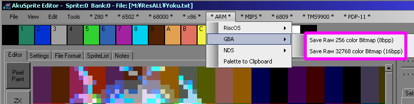 |

| OK, First we need to set up our screen... we're going to use
'Screen mode 4'... this gives a 256 color bitmap screen (1 bytes
per pixel) at ram address 0x06000000 This screen mode only works on Background Layer 2 To turn it on we need to set graphics register x04000000 - bits 0-2 are the Screen mode, bit 10 turns on Background 2 Once the screen is on, we'll fill the screen! The screen starts at 0x06000000 and has 256x192 pixels... where each pixel takes 1 byte and selects a color from the palette. |
 |
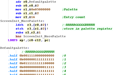
| We're going to define a palette. Each color is defined by a 15 bit value in the format where each pixel takes 2 bytes in the format '-BBBBBGGGGGRRRRR'... with 5 Blue, Green and Red bits - the top bit is unused We store these words to addresses 0x05000000+ - each word is a palette entry |
 |
| Even though 1
pixel takes a single byte we have to write in WORDS -
otherwise both pixels will be set at the same time! You'll have to program accordingly to work around this limitation! |
 |
| These tutorials use a 1 nibble per color standard palette
format in the layout 0x-GRB (one nibble is unused) |
 |
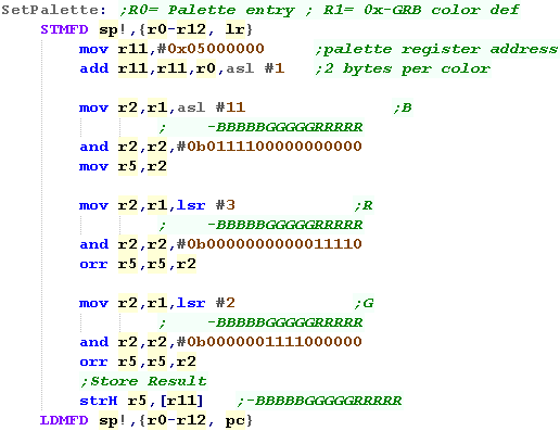
| As mentioned, palette entries take two bytes ,and are kept at
address 0x05000000+ - each word is a palette entry To calculate the destination address, we multiply our palette number (in R0) by two and add to 0x05000000 Each color is defined by a 15 bit value in the format where each pixel takes 2 bytes in the format '0b-BBBBBGGGGGRRRRR'... with 5 Blue, Green and Red bits - the top bit is unused These tutorials use bit format 0b----GGGGRRRRBBBB ... so we need to mask the bits of each channel and move them to the correct position Finally we write the word to the calculated address. |
 |
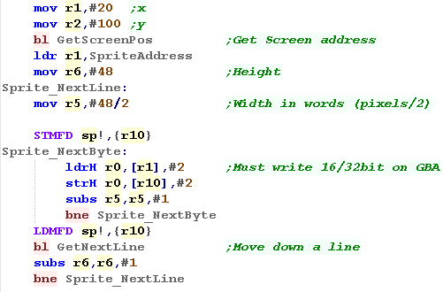
| When we want to draw to the screen we need to calculate the
ram address.. The screen is 240x160 pixels - each pixel is 1 byte, and our screen base is 0x06800000 Therefore our screen formula is: Address = 0x06000000 + (Ypos * 240) + Xpos When we want to move down the screen, we just add 240 to the current screen address. |
|
| When we want to draw to the screen, we calculate the screen
address, and copy each byte of the line to the screen, We then move down the screen, and repeat until the sprite is done. |
 |
| We include the bitmap from a file | 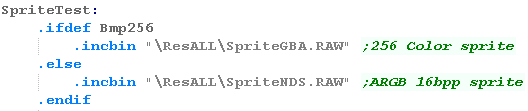 |
| Here is the result! | 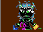 |
| Want to create a valid file? you can use my AkuSprite Editor, it's free and open source, and included in the sources file. | |

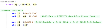
| The NDS has two graphics engines - Engine A is the most powerful
and can do 3D - Engine B is around the same spec as a GBA Each Engine can only drive one screen - so we need both for dual screens (That's why most games have simple graphics on one screen) Before we can use either, we need to turn them on with reg 0x4000304 |
 |
| We'll allocate Engine A to the top screen, and
Engine B to the bottom Though A is more powerful, we're only doing simple graphics so it won't make much difference. |
 |
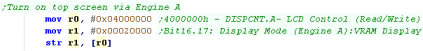
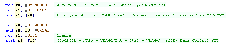
| Engine A can map an area of normal memory straight onto the
screen as a 16 bit 256x192 image (VRAM Display) We do this by setting bits 16 and 17 of 0x4000240 to 'Mode 2' |
 |
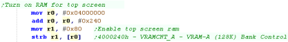
| The last command enabled the screen, but we must also turn on
it's ram... We do this with 0x4000240 Now Words written to 0x06800000+ will set pixels of the top screen in format -BBBBBGGGGGRRRRR |
 |
 |
If you only want one screen - we're done! If you want two, it's tricky... Engine B can't do RAM displays as easily, but we can do it in a more tricky way!... read on! |
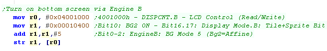
| We're going to set up a 16 bit display on the other screen to -
but engine B cannot do VRAM display... however it can do Affine
mode - this is where an area of memory is used as a
rotatable/scalable bitmap. Engine B uses ports 0x04001000+ We enable Affine on layer BG2 with port 0x04001000 |
 |
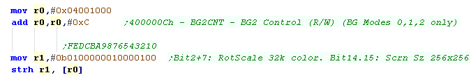
| We need to configure Affine mode with port 0x0400100C We're setting the bitmap to 256x256 (to fill the width of the screen) and 32k (16 bit) color |
 |
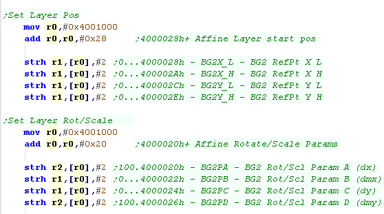
| The screen is on, but it won't work without some default
rotate/scale settings. Here are the basic ones to map a normal 1:1 screen |
 |
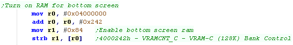
| But wait! We still need to turn the memory on! We do this with 0x4000242, The bottom screen is finally enabled! Now Words written to 0x06200000+ will set pixels of the top screen in format ABBBBBGGGGGRRRRR (A= Alpha - 1=visible) |
 |
We can write to both our screens in almost the same way - the
only difference is the bottom screen uses Alpha in bit 15
(1=Visible)... the top screen doesn't use it
|
 |
|||||||||
| What a lot of effort! The screen is finally, on, clear and ready for us to draw some data! |
 |
| When we want to draw to the screen we need to calculate the
ram address.. The screen is 256x192 pixels - each pixel is 2 bytes, Lines 0-191 have a screen base of 0x06800000 Lines 192-383 have a screen base of 0x06200000 Therefore our screen formula is: Address = Screenbase +(Ypos * 256*2) + Xpos * 2 When we want to move down the screen, we just add 480 to the current screen address. |
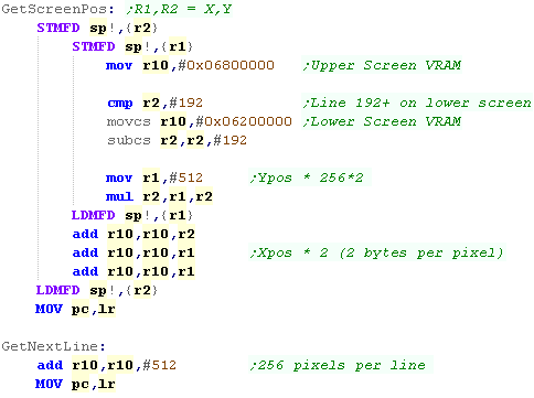 |
| When we want to draw to the screen, we calculate the screen
address, and copy each byte of the line to the screen, We then move down the screen, and repeat until the sprite is done. |
 |
| We include the bitmap from a file |  |
| Here is the result! | 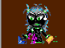 |
| Want to create a valid file? you can use my AkuSprite Editor, it's free and open source, and included in the sources file. | 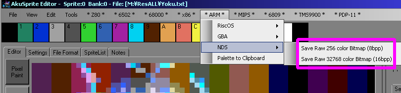 |
|
Key reading on Risc OS |
| We can read from the keyboard with an OS Call with SWI 6
(OSByte) Function 129 (0x81) allows us to read from the keyboard... If we load R1,R2 with a 2 byte delay (R1=L byte R2=H byte) we can get an ASCII key back from the keyboard in R1... the delay can be up to 0x7FFF |
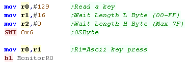 |
| Here we had space pressed (Ascii 32 - 0x20) |  |
| If we want to test a keypress we need to set R2=255... we need
to set R1 to the keypress EORed with 255 (255^keypress) The Keypresses are not ASCII - they are keycodes.... R1 returns 255 if the key is pressed, 0 if it is not. In this example we're testing Up, Down, Left and Right and showing a Letter for each direction |
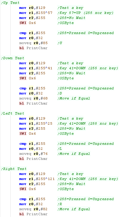 |
| Here UP and RIGHT were held down, so we show U and R |  |
| Esc:112 | F1: 113 | F2: 114 | F3: 115 | F4: 20 | F5: 116 | F6: 117 | F7: 22 | F8: 118 | F9: 119 | F10:30 | F11: 28 | F12: 29 | Print: 32 | ScrlLk:31 | Brk:44 | ||||||||
| `: 45 | 1: 48 | 2: 49 | 3: 17 | 4: 18 | 5: 19 | 6: 24 | 7: 36 | 8: 21 | 9: 38 | 0: 39 | -: 23 | =: 93 | Pnd: 46 | Bksp: 47 | Ins: 61 | Home:62 | PgUp:63 | NmLk: 77 | /: 74 | *: 91 | #: 90 | ||
| Tab: 96 | Q: 16 | W: 33 | E: 34 | R: 51 | T: 35 | Y: 68 | U: 53 | I: 37 | O: 54 | P: 55 | [: 56 | ]: 88 | \: 120 | Del: 89 | Copy:105 | PgDown:78 | 7: 27 | 8: 42 | 9: 43 | -: 59 | |||
| Ctrl: 14 | A: 65 | S: 81 | D: 50 | F: 67 | G: 83 | H: 84 | J: 69 | K: 70 | L: 86 | ;: 72 | ': 79 | Retn: 73 | 4: 122 | 5: 123 | 6: 26 | +: 58 | |||||||
| Shift: 03 | Z: 97 | X: 66 | C: 82 | V: 99 | B: 100 | N: 85 | M: 101 | ,: 102 | .: 103 | /: 104 | Shift:06 | U:57 | 1: 107 | 2: 124 | 3:108 | Enter: 60 | |||||||
| Caps: 64 | Alt: 25 | Spc: 98 | Alt:28 | Ctrl: 17 | L:25 | D:41 | R:121 | 0:106 | .:76 |
 |
Joypad Reading on the Gameboy Advance |
| Reading in the GBA buttons is super easy!... just read in from
0x4000130... you'll get a word back with all the keys in the
format %------LRDULRSsBA Um... that's it! |
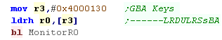 |
| A bit is 1 if the key isn't pressed.. 0 if the key is pressed Here we pressed Down and A |
 |
| The 'GBA' key reading we see here is the same
on the NDS... Which is nice and easy! Unfortunately, reading the other keys is not!... for some reason the NDS only keys are a right pain! |
 |
 |
Joypad Reading on the Nintendo DS |
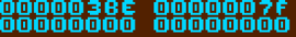
| Reading in the GBA buttons of the NDS is the same as the GBA...
just read in from 0x4000130... you'll get a word back with all the
keys in the format %------LRDULRSsBA |
|
| A bit is 1 if the key isn't pressed.. 0 if the key is pressed Here we pressed Down and A (0x7BE) |
 |
| We usually use the ARM9 for our program, but this CPU cannot read
the extra buttons... we have to write a separate program for the
ARM7 (specified by the ROM header) and write the read data to the
shared memory 0x02F00000+ To read in the extra keys we read from ARM7 address 0x4000136... this reads X and Y , 'PenDown', a special 'Debug' function and the 'lid closed' sensor in the format %--------HP--D-YX |
on the ARM7: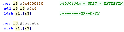 |
| Here we pressed the X key (0x7E) | 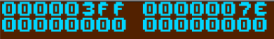 |
|
PEN Reading on the Nintendo DS |
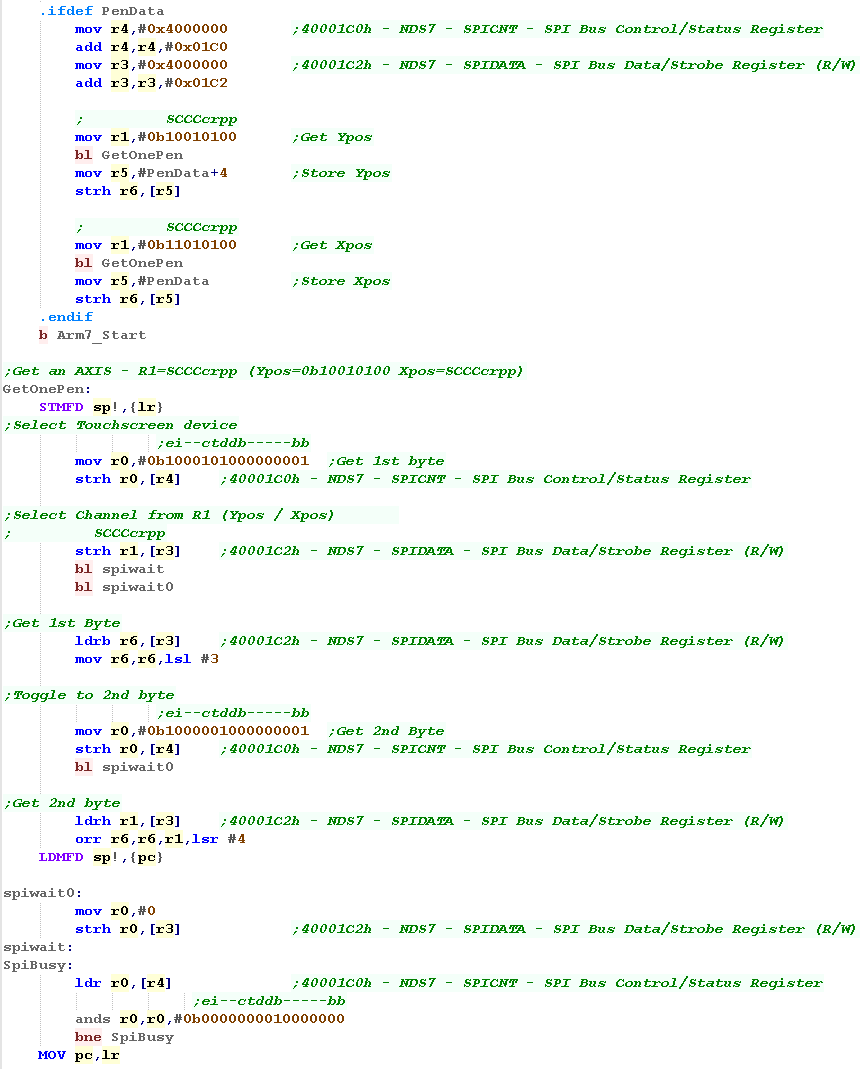
| Accessing the PEN pos can only be done from the ARM7 - and its not
entirely easy!
the X and Y pos use 12 bits each, but
we can only load them 8 bits at a time, via a serial bus....
0x40001C0 - SPICNT - SPI Bus
Control/Status Register
0x40001C2 - SPIDATA - SPI Bus Data/Strobe Register Here is the sequence for reading an
axis...
#0b1000101000000001 ->
SPICNT (Select Touchscreen)
#0b11010100 -> SPIDATA (Xpos) ...
OR .... #0b10010100 -> SPIDATA (Ypos)
SPICNT -> Wait for Bit 7 of SPICNT
to become 0
#0 -> SPIDATA
SPICNT -> Wait for Bit 7 of SPICNT
to become 0
SPIDATA-> top 8 bits of axis
HHHHHHHH
#0b1000001000000001 ->SPICNT (Get
2nd byte)
#0 -> SPIDATA SPICNT -> Wait for Bit 7 of SPICNT
to become 0
SPIDATA-> bottom 4 bits of axis
LLLL0000
|
 |
| Here the X and Y position... We pressed the pen in the bottom right of the touchpad. | 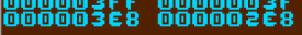 |
|
Lesson
P6 - Sound on the Gameboy Advance The GBA retains the same basic functions of the Gameboy Color... Here we'll learn how to make simple sounds for our games. |
|
|
|
Introducing ChibiSound!
| In these tutorials we're going to
create an 'amazing' new sound API to rival Directsound!!!... well at
least the functionality won't break like Directsound 3D did! Well, no it won't... what it will do is take a byte value from 0-255, and make a sound of selectable pitch, with noise or half volume in a similar way on all our systems! This was created for Grime Z80, and allows common sound code to give similar effects on all the systems! All we do is load the accumulator with a value, and call ChibiSound! Of course, this won't be enough to make musicbut it will give us some simple SFX, and make it easy to compare doing simple tasks on our various systems! |
|
Sound Ports
| Port | Name | Description | Bits | Details |
| 4000060h | SOUND1CNT_L | Channel 1 Sweep register | ---------TTTDSSS | S=sweep shift D=direction T=Time |
| 4000062h | SOUND1CNT_H | Channel 1 Duty/Length/Envelope (NR11 | VVVVDSSSWWLLLLLL | L=length W=wave pattern duty S=envelope Step D= env direction V=Volume |
| 4000064h | SOUND1CNT_X | Channel 1 Frequency/Control | IL---FFFFFFFFFFF | I=Init sound L=no loop F=Frequency |
| 4000068h | SOUND2CNT_L | Channel 2 Duty/Length/Envelope (NR21 | VVVVDSSSWWLLLLLL | L=length W=wave pattern duty S=envelope Step D= env direction V=Volume |
| 400006Ch | SOUND2CNT_H | Channel 2 Frequency/Control | IL---FFFFFFFFFFF | I=Init sound L=no loop F=Frequency |
| 4000070h | SOUND3CNT_L | Channel 3 Stop/Wave RAM select (NR30) | -------PBD----- | D=Dimension B=Bank P=Play |
| 4000072h | SOUND3CNT_H | Channel 3 Length/Volume | FVV-----LLLLLLLL | L=sound Length V=volume F=Force |
| 4000074h | SOUND3CNT_X | Channel 3 Frequency/Control | IL---FFFFFFFFFFF | I=Init sound L=no loop F=Frequency |
| 4000078h | SOUND4CNT_L | Channel 4 Length/Envelope | VVVVDSSS--LLLLLL | L=length S=envelope Step D= env direction V=Volume |
| 400007Ch | SOUND4CNT_H | Channel 4 Noise Frequency/Control | IL------SSSSCRRR | R=dividing Ration, C=Counter S=shify clock freq L+no Loop I=Init sound |
| 4000080h | SOUNDCNT_L | Control Stereo/Volume/Enable | LLLLRRRR-lll-rrr | LR=Channel on lr=master vol(7=max) |
| 4000082h | SOUNDCNT_H | Control Mixing/DMA Control | BBBBAAAA-ba-VV | |
| 4000084h | SOUNDCNT_X | Control Sound on/off | M---4321 | M=Master ON 1234 (Read) = Sound on flag |
| 4000088h | BIOS SOUNDBIAS | Sound PWM Control | AA----BBBBBBBBB- | A=Amplitude B=Bios |
| 4000090h | WAVE_RAM | 16 Bytes | 1111222233334444 | 4 bit sample data |
| 40000A0h | FIFO_A | Channel A FIFO | ----DDDD----DDDD | D=Wawave Data |
| 40000A4h | FIFO_B | Channel B FIFO | ----DDDD----DDDD | D=Wawave Data |
Writing ChibiSound
| First we need to turn on the sound hardware, we do this with bit 7 of 0x4000084 | 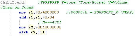 |
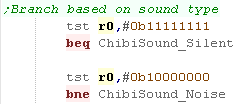
| Depending if we're making a tone or a noise, we need to branch We'll use Channel 1 for tones, and Channel 4 for noise |
 |
| If we're making a tone we use
channel 1 for the sound. We need to select a volume for channel 1 with the top 4 bits of 0x4000062 We need to select a frequency for channel 1 with the 12 bits of 0x4000064 - we also need to set the top bit to 1 to make the sounds start We need to set the channel to on, by setting the Left+Right bits for channel 1 to 1 (on) in the top 8 bits of 0x4000080h (the mixer)... we also set the bits for the 'master volume' L+R to 1 in bits 0-7... the max volume is 7 |
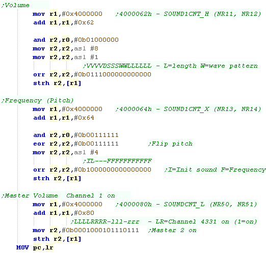 |
| If we're making a noise we use channel 4
(the noise channel) We need to select a volume for channel 4 with the top 4 bits of 0x4000078 The noise frequency is set with bits 4-7 of %400007Ch Once again we need to set the channel to on, by setting the Left+Right bits for channel 4 to 1 (on) in the top 8 bits of 0x4000080h (the mixer)... we also set the bits for the 'master volume' L+R to 1 in bits 0-7... the max volume is 7 |
 |
| If we want to silence sound, we turn off all the channels of the mixer with 0x4000080h | 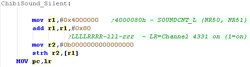 |
| Of course, the GBA can
do more than just simple beeps, it's capable of playing digital
sound samples. But for now we'll make do with some basic beeps. |
|
Introducing ChibiSound!
| In these tutorials we're going to
create an 'amazing' new sound API to rival Directsound!!!... well at
least the functionality won't break like Directsound 3D did! Well, no it won't... what it will do is take a byte value from 0-255, and make a sound of selectable pitch, with noise or half volume in a similar way on all our systems! This was created for Grime Z80, and allows common sound code to give similar effects on all the systems! All we do is load the accumulator with a value, and call ChibiSound! Of course, this won't be enough to make music but it will give us some simple SFX, and make it easy to compare doing simple tasks on our various systems! |
|
Sound Registers (ARM7)
Like pen control, the main ARM9 CPU cannot access the sound hardware... so we'll program a routine on the ARM7 and use a couple of bytes of shared ram to pass commands to the Arm7 routine
There are 16 sound channels, with addresses like 40004x0h where x is a channel from 0-F
| Address | Bytes | Name | Description | Bits | Notes |
| 4000304h | 2 | POWCNT2 | Sound/Wifi Power Control Register (R/W) | ------WS | S=Sound on W=Wifi on |
| 40004x0h | 4 | SOUNDxCNT | Sound Channel X Control Register (R/W) | SFFRRWWW-PPPPPPPH-----DD-VVVVVVV | S=Start F=Format R=Repeat W=Wave duty P=Panning H=Hold D=volume Div V=Volume |
| 40004x4h | 4 | SOUNDxSAD | Sound Channel X Data Source Register (W) | -----AAAAAAAAAAAAAAAAAAAAAAAA00 | A=Address of sample |
| 40004x8h | 2 | SOUNDxTMR | Sound Channel X Timer Register (W) | FFFFFFFFFFFFFFFF | F=Frequency |
| 40004xAh | 2 | SOUNDxPNT | Sound Channel X Loopstart Register (W) | LLLLLLLLLLLLLLLL | L=Loop Start |
| 40004xCh | 4 | SOUNDxLEN | Sound Channel X Length Register (W) | LLLLLLLLLLLLLLLL | L=Length |
| 4000500h | 2 | SOUNDCNT | Sound Control Register (R/W) | M-31RRLL-VVVVVVV | M=Master on 31=output 31 to mixer RRLL=output from V=master Volume |
| 4000504h | 2 | SOUNDBIAS | Sound Bias Register (R/W) | -------BBBBBBBBBB | B=Sound Bias |
| 4000508h | 1 | SNDCAP0CNT | Sound Capture 0 Control Register (R/W) | S---FEsC | S=Start F=Format R=Repeat s=source C=Control |
| 4000509h | 1 | SNDCAP1CNT | Sound Capture 1 Control Register (R/W) | S---FEsC | |
| 4000510h | 4 | SNDCAP0DAD | Sound Capture 0 Destination Address (R/W) | -----AAAAAAAAAAAAAAAAAAAAAAAA00 | A=Address of Capture |
| 4000514h | 2 | SNDCAP0LEN | Sound Capture 0 Length (W) | LLLLLLLLLLLLLLLL | L=Length |
| 4000518h | 4 | SNDCAP1DAD | Sound Capture 1 Destination Address (R/W) | -----AAAAAAAAAAAAAAAAAAAAAAAA00 | |
| 400051Ch | 2 | SNDCAP1LEN | Sound Capture 1 Length (W) | LLLLLLLLLLLLLLLL | L=Length |
Writing ChibiSound
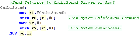
| We're using 2 bytes of shared RAM to pass commands to the ARM7 The first byte is the 'chibisound' byte in the format %TVPPPPPP where T=tone (Tone/Noise) V=Volume (Low/High) P=Pitch The second is the 'Action' byte - if it's zero, the ARM7 will do nothing, if it's nonzero, the ARM7 will process the first byte, then set the second back to zero |
 |
The ChibiSound Driver on the ARM7
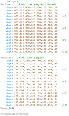
| We're going to need 2 sound samples. One is a simple Tone (A square wave)... the other is a random noise sample. |
 |
| First we check the second 'action' byte If it's zero, we have nothing to do, so we skip processing If it's one, we have commands! |
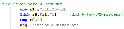 |
| Next we check the ChibiSound byte, if it's zero, we're going to mute sound we do this by setting the master volume to zero with the sound control register 0x4000500 | 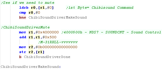 |
| if we're going to play a sound, we first make sure the sound hardware is enabled by writing #1 to 0x4000304 | 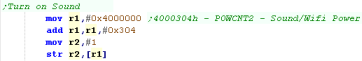 |
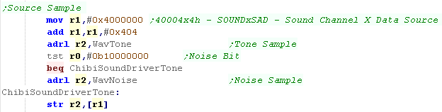
| Whatever sound we make, we'll use channel 0 for our sounds. Next we need to decide whether to use our Tone sample or Noise sample - this depends on the top bit of the ChibiSound command... we do this with 0x4000404 Note: The sound sample must be aligned to a 32 bit boundary (4 byte) |
 |
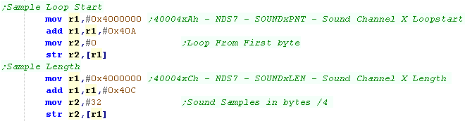
| Next we need to set the length of the
sample (in 32 bit words.... so Bytes /4) Both our samples are 128 bytes - so 32 words.... we do this with sound reg 0x400040C We want the whole sample to loop (not just part) so we set the 'Loop from' to #0 in 0x400040A |
 |
| Ok, next we need to set the frequency (pitch) of the playback, we do this with reg 0x4000408h | 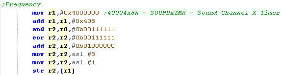 |
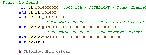
| Next we need to set the channel Volume ,
set the Repeat (1=InfLoop),Panning
(64=center) and Format (0=8Bit
Signed) We do all this with 4000400h The sound will now play! |
 |
|
Remember... these commands only work from
the ARM7 - you need to define a separate program for that CPU to
run in the header... Don't know how to do that? No problem! check out the files in the sources download! What? You can't be bothered? Sheesh! Well I guess you didn't really want to know then! |
Setting up the tilemap
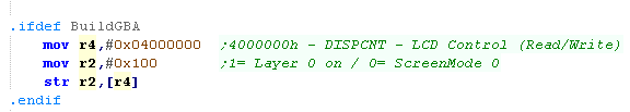
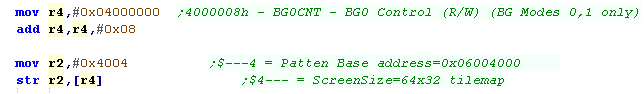
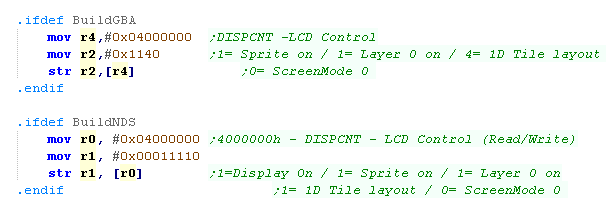
| First we need to enable the screen layer, and set screen mode 0
(16 color Tilemap) we do this with port 4000000h (This command is slightly different on the NDS) |
 |
| Next we need to configure the tilemap... We're going to set the
base for the tile patterns at address 6004000h... We're also going to set the tilemap size to 64x32... The visible screen is 32x24, but this isn't enough for the screen to scroll. |
 |
 |
The
64x32 tilemap is actually made up of 2x 32x32 tilemaps! The Left hand half of the tilemap is at 06000000h The Right hand half of the tilemap is at 06000800h |
Setting up the tilemap
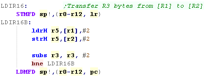
| We're going to define a function LDIR16 to transfer data in 16 bit
chunks. This will Transfer R3 bytes from [R1] to [R2] Working in Halfwords rather than bytes works best on the GBA as some VRAM functions will malfunction if we write bytes (We could also use Words) |
 |
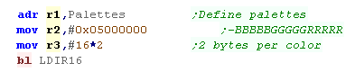
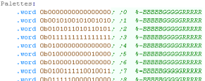
| First we'll set up our palette - each palette uses 16 colors... we
write halfwords to 05000000h to define each color in the format
0b-BBBBBGGGGGRRRRR (5 bits per channel) |
  |
| Next we're going to define our tile patterns (the bitmap data of
the tiles) Each tile is 8x8 and uses 4 bits per pixel... They are in 'Linear' format NOT bitplanes, so each nibble of a byte defines the color. because of the settings we sent to 4000008h, Tile pattern 0 is at address 06004000h |
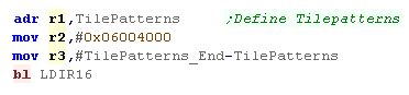 |
| You can export Tile bitmap data in the correct format with my AkuSprite Editor. | 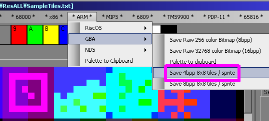 |
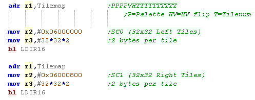
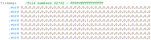
| We're going to transfer the tile numbers we're going to show into
the two 32x32 tilemaps The Left hand side half is at 6000000h The Right hand side half is at 6000800h Each tile is a single word in the format 0bPPPPVHTTTTTTTTTT, where P=Palette HV=HV flip T=Tilenum |
  |
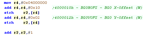
| We can scroll the tilemap with two registers 4000010h will scroll horizontally 4000012h will scroll vertically |
 |
| Here is the tilemap scrolling! |  |
| The
DS version is almost the same, we just need to do a bit more
initialization to get the system set up. |
|
Using the Tilemap on the Nintendo DS
| First we need to turn on the hardware, this is the same as our bitmap example | 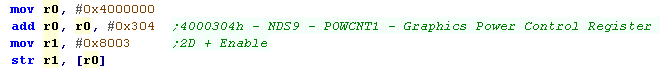 |
| Next we need to configure the tilemap with 4000000h, but this
register has changed slightly with the NDS We also need to turn on VRAM for our tilemap, we do this with 4000240h |
 |
| The Tilemap will now scroll on the NDS too! | 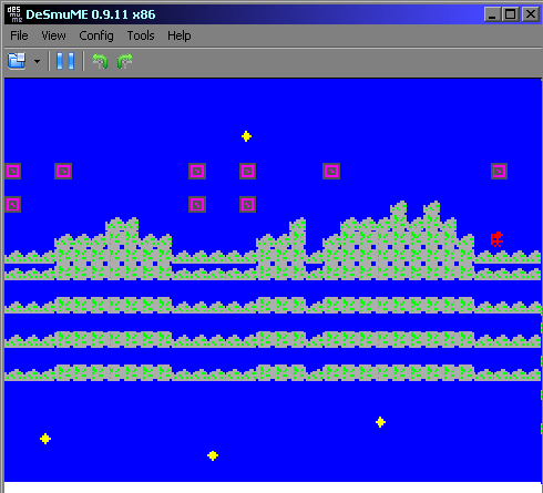 |
1D Sprites and 2D Sprites
| Sprite data for sprites larger than 8x8 can be organized on one of
two formats. In 1D mode, Sprite patterns are organized in a linear format (this is the format this example uses) If we were to show a crosshair from sprite data it would use tiles 1,2,3,4 In 2D mode, Sprite patterns are organized according to a 32,32 grid. If we were to show a crosshair from sprite data it would use tiles 1,2,33,34 |
1D Mode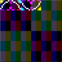 |
2D Mode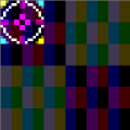 |
Enabling Hardware Sprites
| The Hardware sprites don't use the same color palettes as the
Tilemap, Hardware Sprite palettes are defined by addresses 5000200h+ |
 |
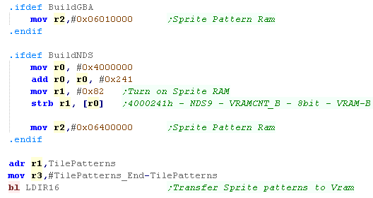
| Next We need to define our sprite patterns (We're using the same
data as the tilemap. On the GBA we need to transfer these to address 6010000h On the NDS we need to transfer these to address 6400000h... BUT we first need to turn on this VRAM with port 4000241h |
 |
| We need to turn on the screen, and enable the sprites (selecting
1D tiles) This is done with port 4000000h, but the settings are slightly different |
 |
|
We're going to create some
simple (unrotated) sprites, The GBA and NDS are capable of
more, but it's tricky, and it's outside of the scope of what
we'll try to do here. |
Enabling Hardware Sprites
Hardware sprites are defined by 3 words... there are 128 in total.
Sprites are defined with 6 bytes from 7000000h Onwards... there are two
bytes after each sprite definition which are used by rotation settings
Sprite 0 is defined by 7000000h+,Sprite 1 is defined by 7000008h+,Sprite 1 is defined by 7000010h+ and so on.
| H Byte | L Byte | ||||||||||||||||
| Vram Address | F
|
E
|
D
|
C
|
B
|
A
|
9
|
8
|
7
|
6
|
5
|
4
|
3
|
2
|
1
|
0
|
|
| 7000000h | S | S | C | M | T | T | D | R | Y | Y | Y | Y | Y | Y | Y | Y | Y=Ypos S=Shape
(Square, HRect, Vrect) C=Colors(16/256)
M=Mosiac T=Transparent D=Disable/Doublesize R=Rotation |
| 7000002h | S | S | V | H | R | R | R | X | X | X | X | X | X | X | X | X | X=Xpos S=Obj
Size (8x8,16x16,32x32,64x64) VH=V/HFlip
R=Rotation parameter |
| 7000004h | C | C | C | C | P | P | T | T | T | T | T | T | T | T | T | T |
T=Tile Number C=Color palette P=Priority |
| 7000006h | Unused by sprite | ||||||||||||||||
The basic size of a Square sprite can be 8x8, 16x16, 32x32 or 64x64,
defined by bits 15-16 of the second word.
However a sprite can be double width, or double height to make a rectangle
defined by bits 15-16 of the first word.
Sprites can be 16 color or 256 color - the pattern data for both can be mixed.
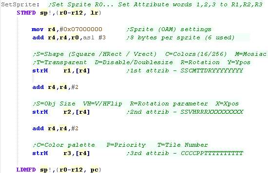
| For the convenience of setting sprites, we'll define a function to
calculate the memory address and transfer register values into the
VRAM addresses. This "SetSprite" function will set sprite number R0 to attribs R1,R2,R3 |
 |
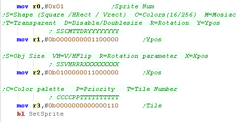
| Lets create a 16x16 16 color sprite. This sprite will use tile 6+
(6,7,8,9) The sprite is a crosshair icon |
 |
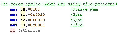
| Lets create a 16x8 rectangular sprite, we'll use Tile 1,2. This will use 2 of the tiles from the tilemap |
 |
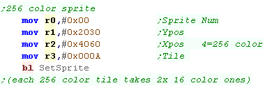
| Lets create a 16x16 16 color sprite. This sprite will use tile 10+
Each 256 color tile takes 2x 16 color ones. The sprite is also a crosshair icon (exported as 8bpp) |
 |
| Here are the Sprite patterns we're importing. | 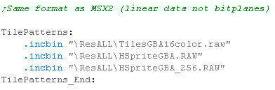 |
| Here is the sample running on the GBA | 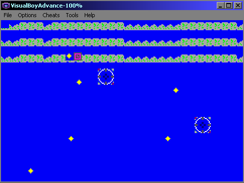 |
| Here is the sample running on the NDS | 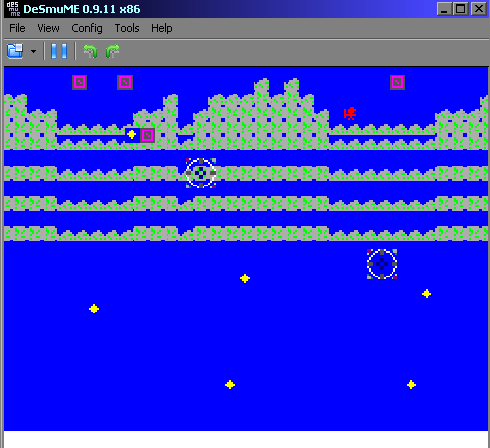 |
| You can export files in the correct format with my AkuSprite Editor (Included in the sources.7z) | |